3D audio delivery accompanying 3D display supported by viewer/listener position and orientation tracking

a technology of orientation tracking and 3d display, applied in the direction of selective content distribution, static indicating devices, instruments, etc., can solve the problems of headache, nausea, eyestrain, etc., and the content, such as two-dimensional text, may be more difficult to read and interpret when displayed three-dimensionally

Inactive Publication Date: 2011-06-30
AVAGO TECH WIRELESS IP SINGAPORE PTE
View PDF99 Cites 84 Cited by
  • Summary
  • Abstract
  • Description
  • Claims
  • Application Information

AI Technical Summary

Benefits of technology

[0022]Methods, systems, and apparatuses are described for supporting 3D audio delivery accompanying 3D display supported by viewer/listener position a

Problems solved by technology

Problems exist with such techniques for viewing three-dimensional images.
For instance, persons that use such displays and systems to view three-dimensional images may suffer from headaches, eyestrain, and/or nausea after long exposure.
Furthermore, some content, such as two-dimensional text, may be more difficult to read and interpret when displayed three-dimensionally.
A disadvantage of parallax barriers is that the viewer must be positioned in a well-defined location in order to exper

Method used


Image

  • 3D audio delivery accompanying 3D display supported by viewer/listener position and orientation tracking
  • 3D audio delivery accompanying 3D display supported by viewer/listener position and orientation tracking
  • 3D audio delivery accompanying 3D display supported by viewer/listener position and orientation tracking

Examples


first embodiment

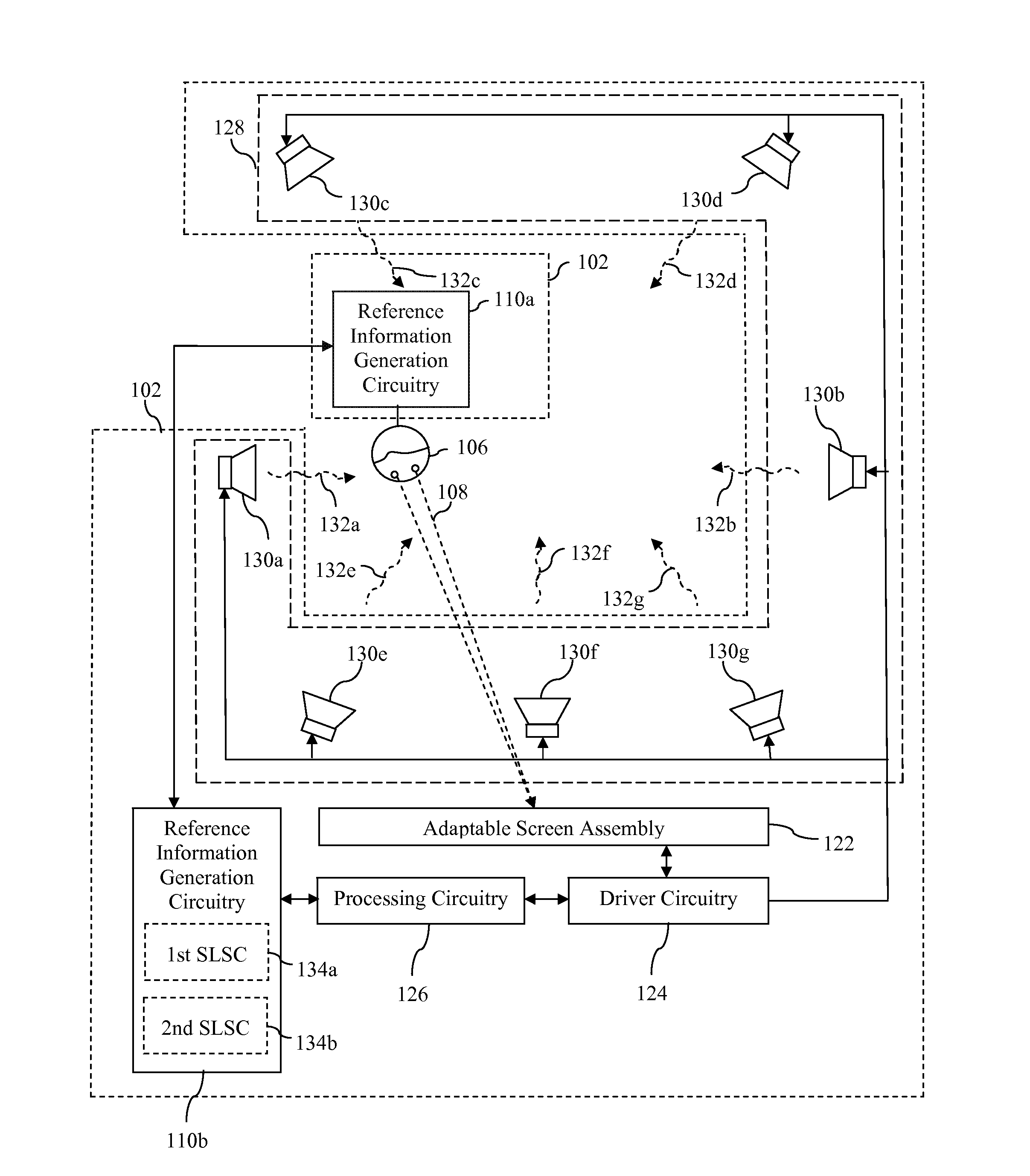
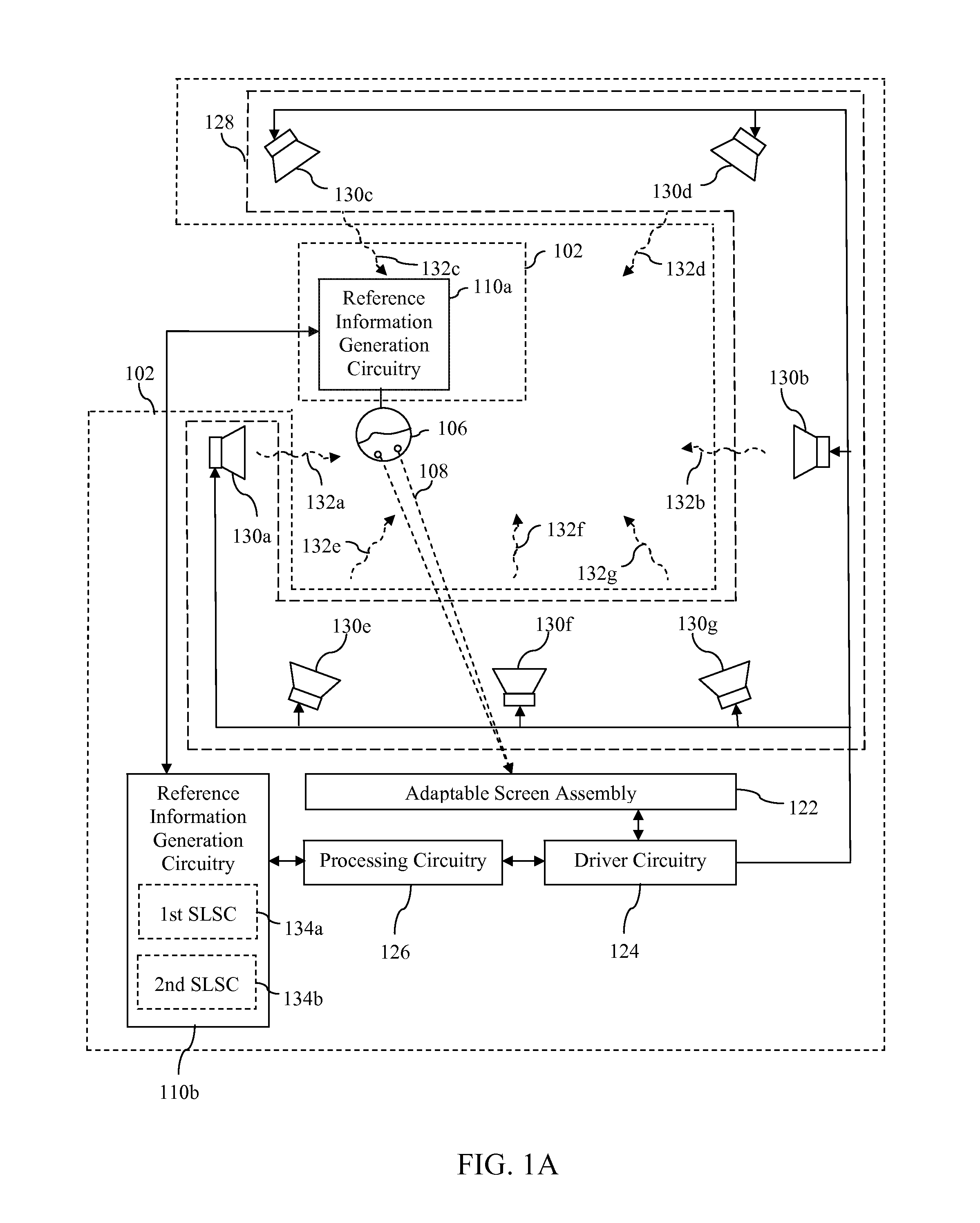
[0093]For example, FIG. 3 is a block diagram of media system 102 in which reference information generation circuitry 110a and 110b jointly implement a triangulation technique to determine an estimated location of viewer 106 relative to adaptable screen assembly 122. As shown in FIG. 3, in accordance with this embodiment, reference information generation circuitry 110a includes a transmitter 306 that is operable to transmit a location tracking signal 308. Location tracking signal 308 may comprise, for example, a radio frequency (RF) signal or other wireless signal. In further accordance with the embodiment shown in FIG. 3, reference information generation circuitry 110b includes a plurality of receivers 3021-302N and triangulation circuitry 304 connected thereto. Receivers 3021-302N are operable to receive corresponding versions 3101-310N of location tracking signal 308. Triangulation circuitry 304 is operable to determine an estimated location of viewer 106 based on characteristics ...

second embodiment

[0096]FIG. 4 is a block diagram of media system 102 in which reference information generation circuitry 110a and 110b jointly implement a triangulation technique to determine an estimated location of viewer 106 relative to adaptable screen assembly 122. As shown in FIG. 4, in accordance with this embodiment, reference information generation circuitry 110b includes a plurality of transmitters 4021-402N that are operable to transmit a corresponding location tracking signal 4121-412N. Location tracking signals 4121-412N may comprise, for example, RF signals or other wireless signals. In further accordance with the embodiment shown in FIG. 4, reference information generation circuitry 110a includes a plurality of receivers 4061-406N and triangulation circuitry 408 connected thereto. Receivers 4061-406N are operable to receive corresponding location tracking signals 4121-412N. Triangulation circuitry 408 is operable to determine an estimated location of viewer 106 based on characteristic...


PUM


Abstract

Techniques are described herein for supporting 3D audio delivery accompanying 3D display supported by viewer/listener position and orientation tracking. For example, audio content is configured to have a spatial orientation that accords with an orientation of a viewer. A spatial orientation of audio content is a configuration of the audio content in which characteristics of respective portions of the audio content, which correspond to respective speakers, indicate an orientation of ears of a viewer/listener with respect to sound source(s) that correspond to (e.g., are depicted in) a three-dimensional view. Such a characteristic may include an amplitude of sound that corresponds to a sound source and/or a delay associated with the sound that corresponds to the sound source.

Description

CROSS-REFERENCE TO RELATED APPLICATIONS[0001]This application claims the benefit of U.S. Provisional Application No. 61 / 291,818, filed on Dec. 31, 2009, which is incorporated by reference herein in its entirety.[0002]This application also claims the benefit of U.S. Provisional Application No. 61 / 303,119, filed on Feb. 10, 2010, which is incorporated by reference herein in its entirety.[0003]This application is also related to the following U.S. Patent Applications, each of which also claims the benefit of U.S. Provisional Patent Application Nos. 61 / 291,818 and 61 / 303,119 and each of which is incorporated by reference herein:[0004]U.S. patent application Ser. No. 12 / 774,225, filed on May 5, 2010 and entitled “Controlling a Pixel Array to Support an Adaptable Light Manipulator”;[0005]U.S. patent application Ser. No. 12 / 774,307, filed on May 5, 2010 and entitled “Display with Elastic Light Manipulator”;[0006]U.S. patent application Ser. No. 12 / 845,409, filed on Jul. 28, 2010, and entit...

Claims


Application Information

Patent Timeline
IPC IPC(8): H04N13/04
CPCG06F3/14G06F3/0346G09G3/20G09G5/003G09G5/14G09G2300/023G09G2320/028G09G2370/04H04N13/0029H04N13/0048H04N13/0055H04N13/0059H04N13/0404H04N13/0409H04N13/0411H04N13/0447H04N13/0454H04N13/0456H04N13/0468H04N13/0497H04N21/235H04N21/4122H04N21/435H04N2013/0463H04N2013/0465G03B35/24H04N13/0413H04N13/0429H04N13/0484H04S7/303G09G3/003H04N13/361G02B6/00H04N13/00H04N13/139H04N13/161H04N13/189H04N13/194H04N13/305H04N13/31H04N13/312H04N13/315H04N13/332H04N13/351H04N13/359H04N13/366H04N13/383H04N13/398H04N2013/403H04N2013/405
Inventor SESHADRI, NAMBIRAJANKARAOGUZ, JEYHANBENNETT, JAMES D.
Owner AVAGO TECH WIRELESS IP SINGAPORE PTE
Why Eureka
Try Eureka