Holographic Image Display Systems

a display system and holographic technology, applied in the field of holographic head-up displays, can solve the problems of the size and complexity of the optics involved, and achieve the effect of reducing computational costs

Inactive Publication Date: 2011-06-30
LIGHT BLUE OPTICS
View PDF9 Cites 232 Cited by
  • Summary
  • Abstract
  • Description
  • Claims
  • Application Information

AI Technical Summary

Benefits of technology

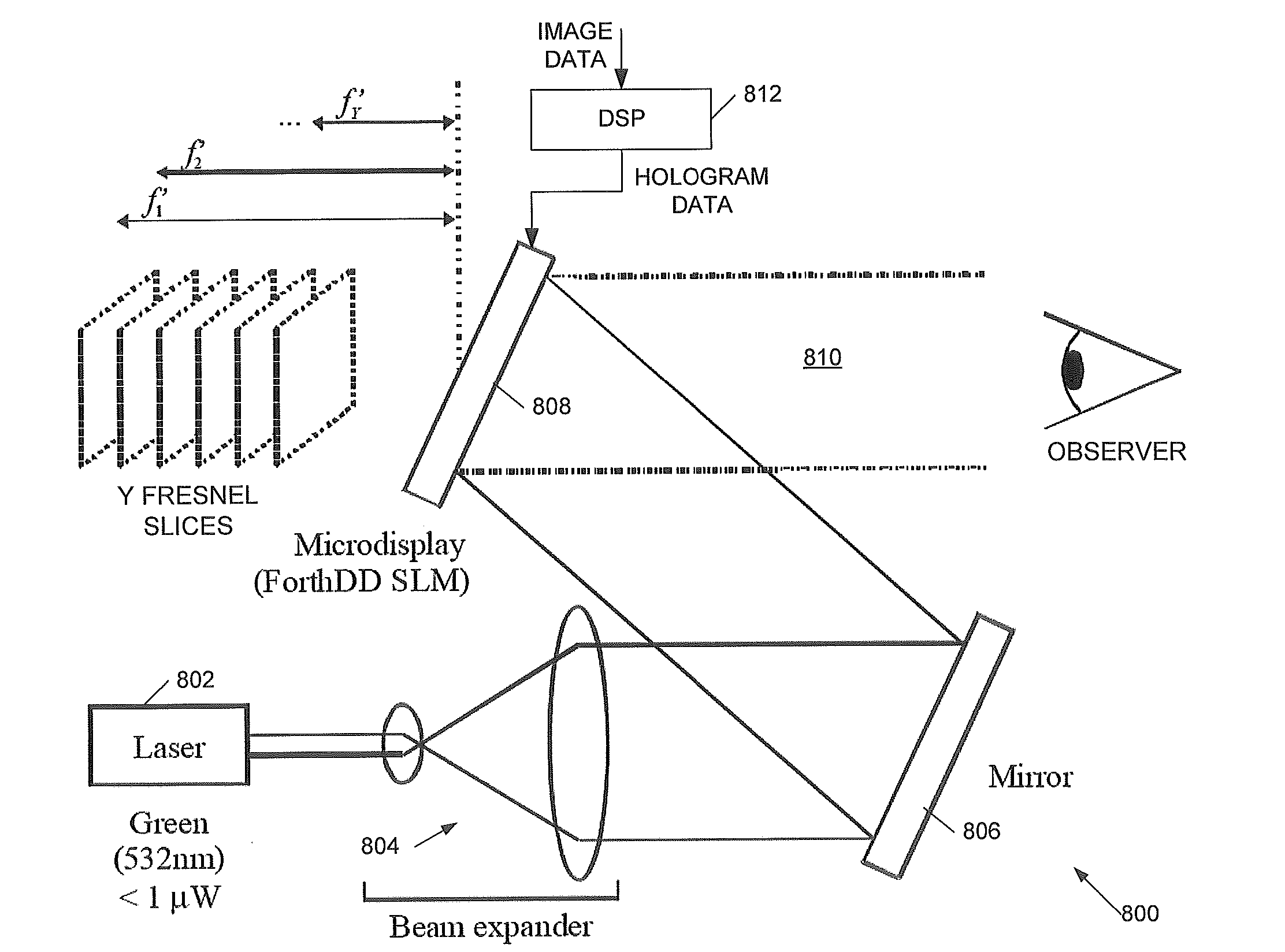
[0038]Embodiments of the display system are thus able to provide a three-dimensional display at substantially reduced computational cost, provided the compromise of a limited number of two-dimensional image slices in the depth (z) direction is accepted. In embodiments by representing the three-dimensional image as a set of two-dimensional image slices, preferably substantially planar and preferably substantially parallel to one another, at successive, preferably regularly increasing steps of visual depth a realistic 3D effect may be created without an impractical computational cost and bandwidth to the SLM. In effect resolution in the z-direction is being traded. Thus in embodiments the z-direction resolution is less than a minimum lateral resolution in the x-or y-direction...

Problems solved by technology

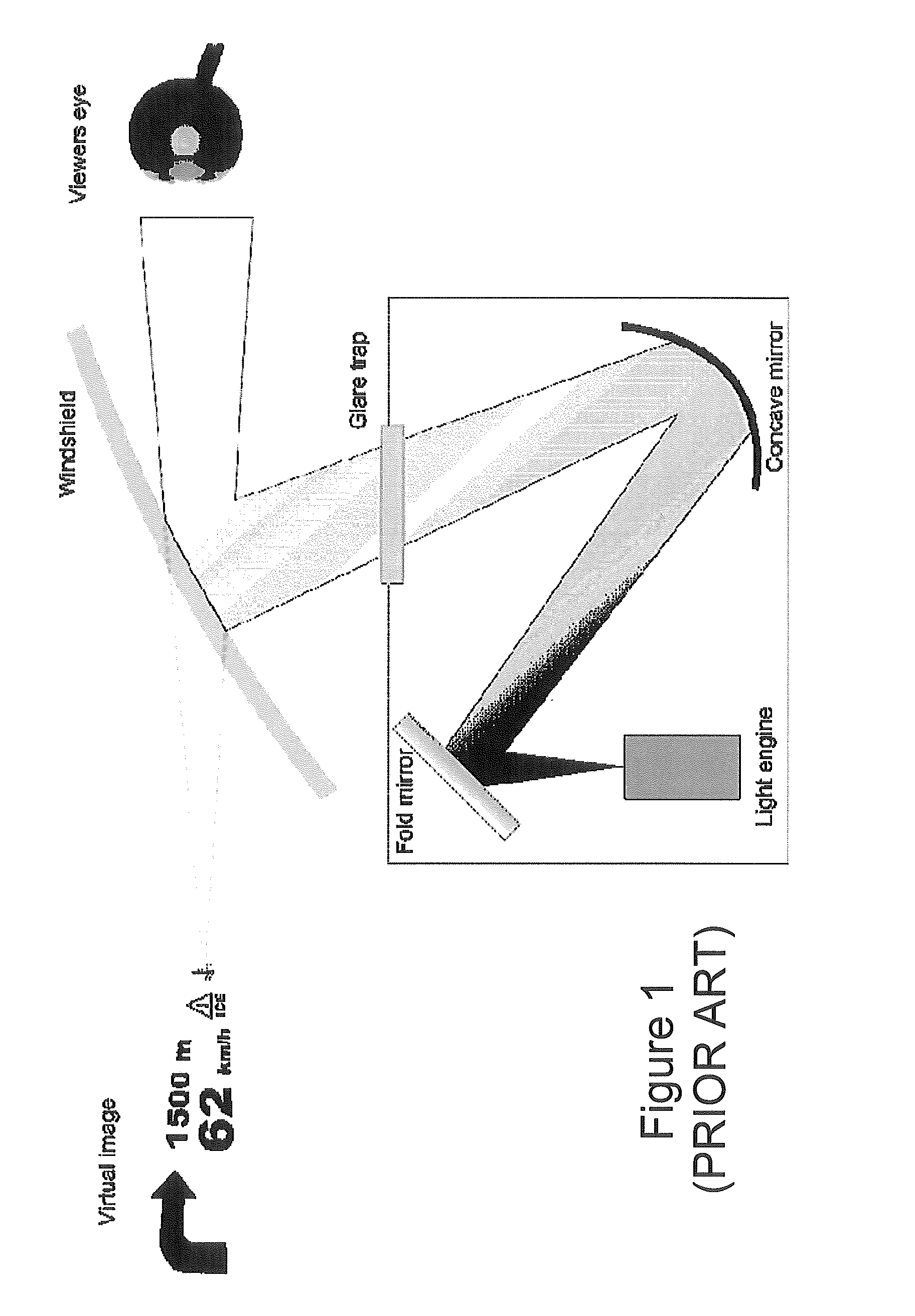
One problem with conventional head-up display...

Method used


Image

  • Holographic Image Display Systems
  • Holographic Image Display Systems
  • Holographic Image Display Systems

Examples


Embodiment Construction

[0051]This invention relates to holographic head-up displays (HUDs), and to three-dimensional holographic image displays, and also to holographic optical sights, and to related methods and processor control code.

[0052]Preferred embodiments of the invention use an OSPR-type hologram generation procedure, and we therefore describe examples of such procedures below. However embodiments of the invention are not restricted to such a hologram generation procedure and may be employed with other types of hologram generation procedure including, but not limited to: a Gerchberg-Saxton procedure (R. W. Gerchberg and W. O. Saxton, “A practical algorithm for the determination of phase from image and diffraction plane pictures” Optik 35, 237-246 (1972)) or a variant thereof, Direct Binary Search (M. A. Seldowitz, J. P. Allebach and D. W. Sweeney, “Synthesis of digital holograms by direct binary search” Appl. Opt. 26, 2788-2798 (1987)), simulated annealing (see, for example, M. P. Dames, R. J. Dow...


PUM


Abstract

The invention relates to holographic head-up displays, to holographic optical sights, and also to 3D holographic image displays. We describe a holographic head-up display and a holographic optical sight, for displaying, in an eye box of the display/sight, a virtual image comprising one or more substantially two-dimensional images, the head-up display comprising: a laser light source; a spatial light modulator (SLM) to display a hologram of the two-dimensional images; illumination optics in an optical path between said laser light source and said SLM to illuminate said SLM; and imaging optics to image a plane of said SLM comprising said hologram into an SLM image plane in said eye box such that the lens of the eye of an observer of said head-up display performs a space-frequency transform of said hologram on said SLM to generate an image within said observer's eye corresponding to the two-dimensional images.

Description

CROSS REFERENCE TO RELATED APPLICATION[0001]This application claims priority to PCT Application No. PCT / GB2009 / 050697 entitled “Holographic Image Display Systems” and filed Jun. 18, 2009, which itself claims priority to Great Britain Patent Application No. GB0905813.2 entitled filed Apr. 6, 2009, and Great Britain Patent Application No. GB0811729.3 filed Jun. 26, 2008. The entirety of each of the aforementioned applications is incorporated herein by reference for all purposes.BACKGROUND OF THE INVENTION[0002]This invention relates to holographic head-up displays (HUDs), and to three-dimensional holographic image displays, and also to holographic optical sights, and to related methods and processor control code.[0003]We have previously described techniques for displaying an image holographically—see, for example, WO 2005 / 059660 (Noise Suppression Using One Step Phase Retrieval), WO 2006 / 134398 (Hardware for OSPR), WO 2007 / 031797 (Adaptive Noise Cancellation Techniques), WO 2007 / 11066...

Claims


Application Information

Patent Timeline
IPC IPC(8): G03H1/08G03H1/22
CPCG02B27/2271G03H2001/2239G03H1/2205G03H1/2249G03H1/2294G03H2001/0088G03H2001/0825G03H2001/221G03H2001/2213G03H2001/2236G03H2001/2242G03H2001/226G03H2001/2263G03H2001/2271G03H2001/2284G03H2001/2297G03H2210/32G03H2210/33G03H2210/454G03H2222/18G03H2223/16G03H2223/19G03H2225/32G03H2227/02G03H2270/55G03H1/0808G02B30/50G02B5/32G02B27/0103G03H1/26G02B30/52
Inventor LACOSTE, LILIANBUCKLEY, EDWARDCABLE, ADRIAN JAMESGIL-LEYVA, DIEGOSTINDT, DOMINIK
Owner LIGHT BLUE OPTICS
Why Eureka
Try Eureka