Supercharge Your Innovation With Domain-Expert AI Agents!

Crystal-less clock generation for radio frequency receivers

Inactive Publication Date: 2011-06-30
QUINTIC MICROELECTRONICS WUXI
View PDF19 Cites 12 Cited by
  • Summary
  • Abstract
  • Description
  • Claims
  • Application Information

AI Technical Summary

Benefits of technology

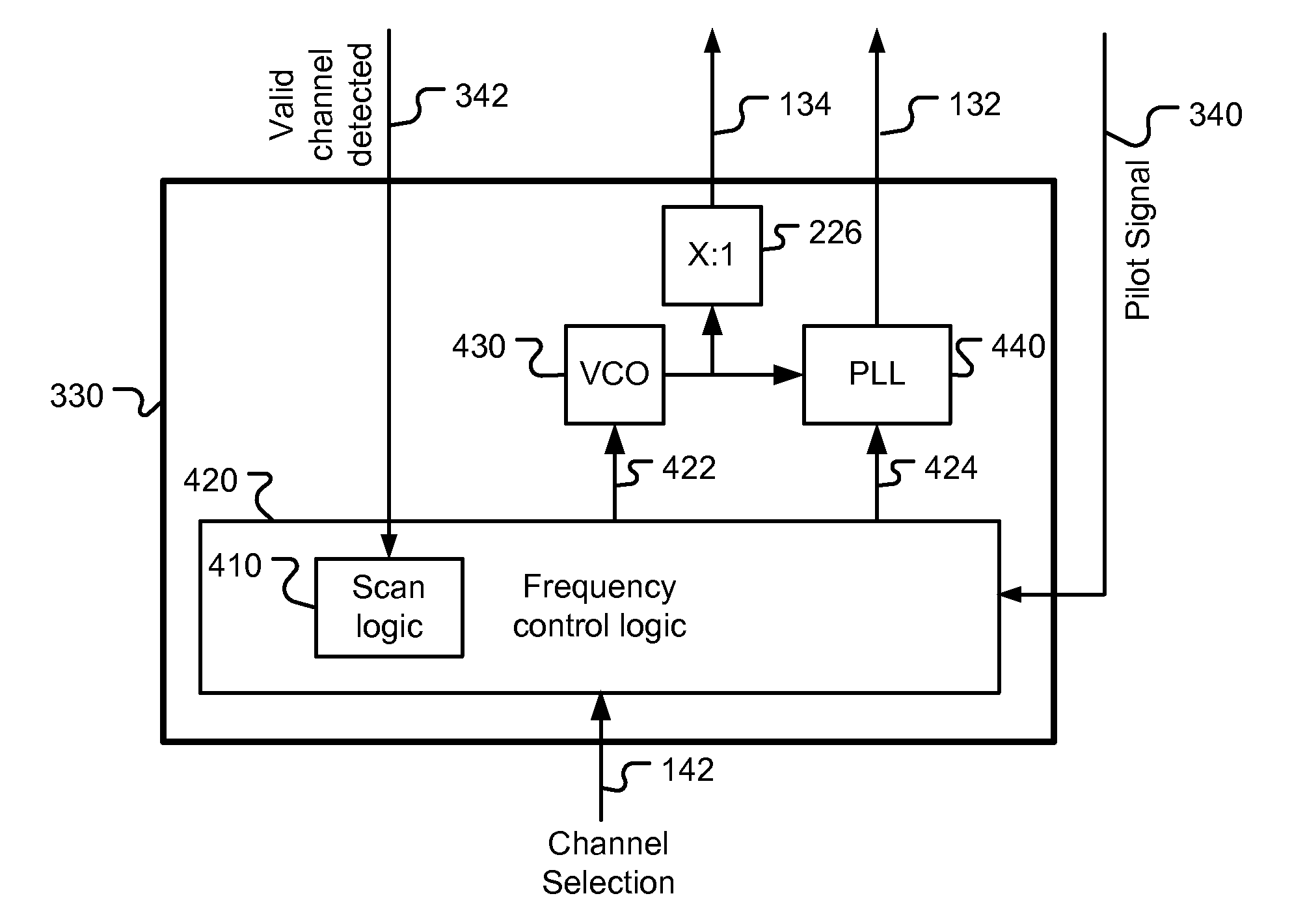
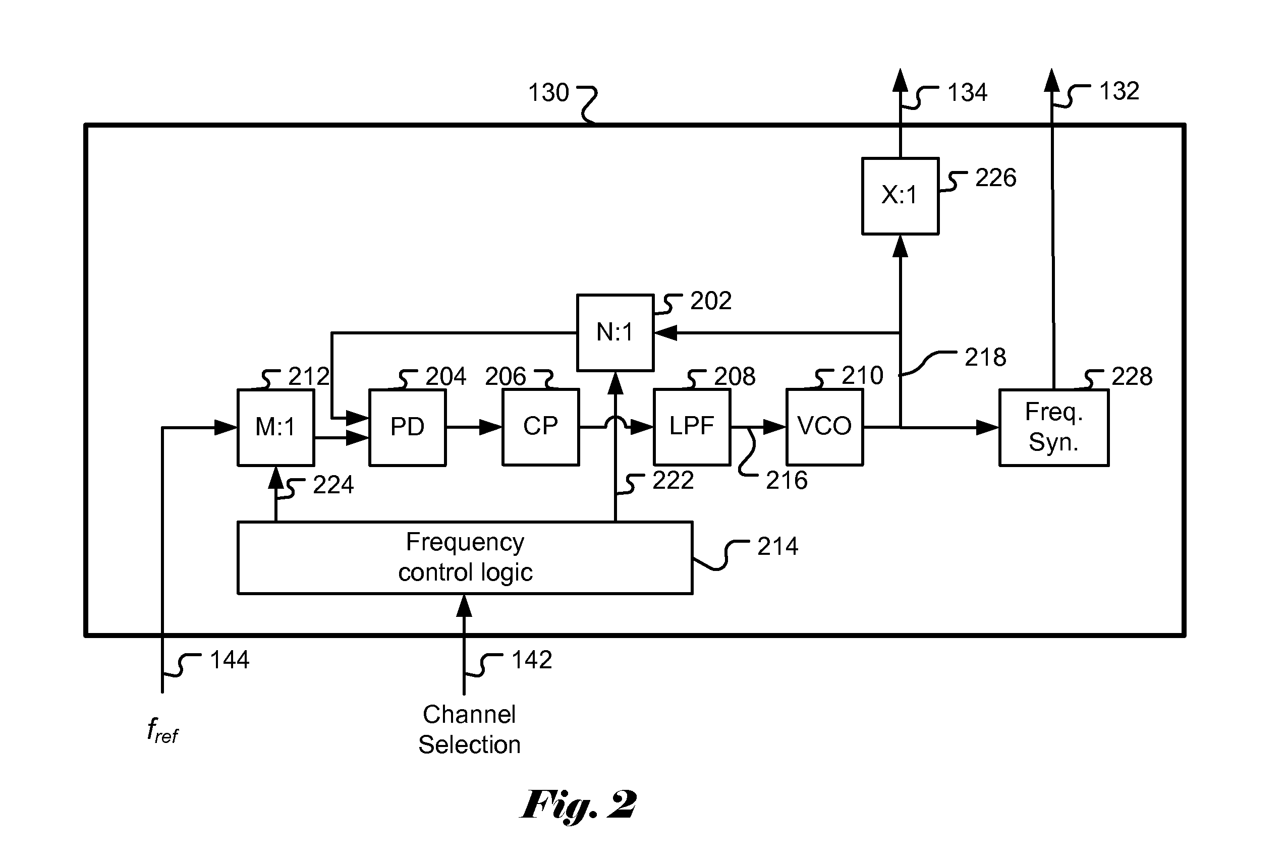
[0008]In yet another embodiment of the present invention, the accuracy of the generated clock can be iteratively improved by repeating the steps a) determining the first control value according to the frequency of the pilot signal and the frequency of the second clock signal, b) adjusting frequency of the first clock signal according to the first control value and a second control value, and c) adjusting the frequency ratio to compensate the change in the frequency of the second clock signal caused by the adjusting frequency of the first clock until a stop criterion is satisfied. In yet another embodiment of the present invention, the accuracy of the generated clock is further improved after the above iterative steps by using the intermediate frequency (IF) counter technique, wherein the frequency of the first clock signal is adjusted according to a value of the IF counter for a tuned channel and a computed IF counter value corresponding to the target frequency of the second clock signal.

Problems solved by technology

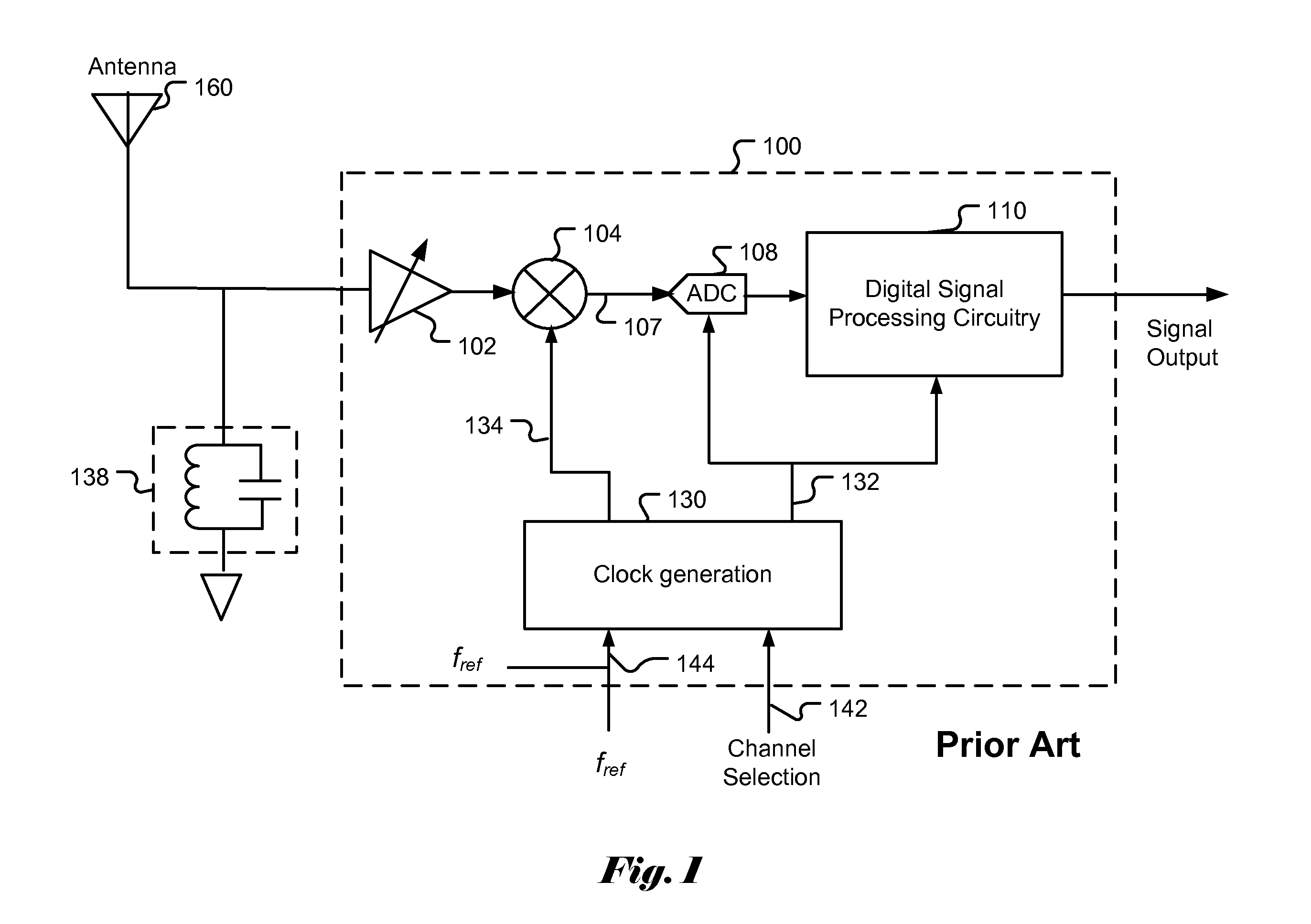
The use of a crystal may increase the system cost.
However, an externally supplied reference clock may not be always available.
For example, in a stand-alone radio receiver application, the external reference clock may not be available.

Method used


Image

  • Crystal-less clock generation for radio frequency receivers
  • Crystal-less clock generation for radio frequency receivers
  • Crystal-less clock generation for radio frequency receivers

Examples


Embodiment Construction

[0020]In the following description, numerous details are set forth to provide a more thorough explanation of embodiments of the present invention. It will be apparent, however, to one skilled in the art, that embodiments of the present invention may be practiced without these specific details. In other instances, well-known structures and devices are shown in block diagram form, rather than in detail, in order to avoid obscuring embodiments of the present invention.

[0021]Reference herein to “one embodiment” or “an embodiment” means that a particular feature, structure, or characteristic described in connection with the embodiment can be included in at least one embodiment of the invention. The appearances of the phrase “in one embodiment” in various places in the specification are not necessarily all referring to the same embodiment, nor are separate or alternative embodiments mutually exclusive of other embodiments. Further, the order of blocks in process flowcharts or diagrams rep...


PUM


Abstract

Systems and methods of clock generation for radio frequency receiver. In radio frequency receiver, the system requires accurate local oscillating (LO) signal and system clocks for proper operation and to ensure high quality performance. In order to achieve accurate LO frequency and system clock, a crystal or and accurate reference clock is provide to the clock generation circuit. How a low-cost receiver, it is desirable to eliminate the requirement for a crystal or an accurate reference clock. The present invention discloses systems and methods to utilize a pilot signal embedded in the transmitted signal. The pilot signal usually has very accurate frequency which is particular true for broadcast system such as FM broadcast. In various embodiments of the present invention, the systems and methods measure the relation between the frequency of the pilot signal and the current clock generated. The measured result is compared with a know relation corresponding to the frequency of the pilot signal and the target clock signal and the result is used to adjust the clock generation circuit.

Description

FIELD OF THE INVENTION[0001]The present invention generally relates to radio frequency receivers and particularly to clock generation for radio receivers that do not require a crystal or a reference clock to generate an accurate reference clock.BACKGROUND[0002]Radio frequency receivers have been widely used in various electronic products such as AM and FM radios, television sets, and GPS (global positioning system) navigation devices. Typically there are multiple channels within the allocated spectrum. In order to receive the signal in a desired channel, the radio frequency input signal is usually mixed with a signal generated by a local oscillator (LO) to translate the incoming radio frequency signal to a lower-frequency signal suitable for further processing using cost effect components and / or for superior performance. The frequency translated signal may be a baseband signal, low-IF (intermediate frequency) or IF signal. The low frequency characteristic of the frequency translated...

Claims


Application Information

Patent Timeline
IPC IPC(8): H04B1/26H03L7/00H03L7/06
CPCH03L7/0805H03L7/0991H03L7/104H03L7/183H03L7/22
Inventor XUAN, PEIQIZHANG, YIFENG
Owner QUINTIC MICROELECTRONICS WUXI
Features
  • R&D
  • Intellectual Property
  • Life Sciences
  • Materials
  • Tech Scout
  • Unparalleled Data Quality
  • Higher Quality Content
  • 60% Fewer Hallucinations
Learn More