Pressure sensor apparatus, system and method

a pressure sensor and pressure sensor technology, applied in the field of pressure sensor apparatus, systems and methods for measuring pressure within the cavity, can solve the problems of intraocular pressure, glaucoma and other visual impairment conditions, and glaucoma progression, and achieve accurate and stable sensor output.

Inactive Publication Date: 2011-06-30
TRONICS NORTH AMERICA
View PDF12 Cites 29 Cited by
  • Summary
  • Abstract
  • Description
  • Claims
  • Application Information

AI Technical Summary

Benefits of technology

[0022]It is another object of the invention to provide implantable pressure sensors, and associated systems and methods, whi

Problems solved by technology

As is well known in the art, intraocular pressure is a risk factor for the development and progression of glaucoma and other visual impairment conditions.
A major drawback of the conventional systems and methods is, however, a patient that presents with acceptable intraocular pressure during clinic office hours may experience intraocular peaks at other times during the day.
An increase in intraocular pressure during a nocturnal period, combined with a decrease in blood pressure, which often occurs during a nocturnal period, can also compromise optic nerve head flow in susceptible individuals.
Although the disclosed intraocular pressure sensor systems provide effective means for measuring intraocular pressure, the systems are highly complex and not suitable for long term use.
In all circumstances, unmonitored and uncontrolled elevated intracranial pressure will eventually lead to visual loss or to cerebral white matter injury and dementia.
There are several drawbacks associated with the noted conventional systems and methods.
The drawbacks include the incumbent risks associated with insertion of medical apparatus, e.g., catheter, tubes, etc., into and through the skull, post-insertion infection, and susceptibility to disruption and dislodgement by the subject and/or hospital personnel.
There are similarly several drawbacks associated with MEMS pressure sensors and asso

Method used


Image

  • Pressure sensor apparatus, system and method
  • Pressure sensor apparatus, system and method
  • Pressure sensor apparatus, system and method

Examples


Embodiment Construction

[0046]Before describing the present invention in detail, it is to be understood that this invention is not limited to particularly exemplified apparatus, systems, materials, structures or methods, as such may, of course, vary. Thus, although a number of apparatus, systems, materials, structures and methods similar or equivalent to those described herein can be used in the practice of the present invention, the preferred apparatus, systems, materials, structures and methods are described herein.

[0047]It is also to be understood that the invention is not limited to any particular application used herein in connection with a described embodiment of the invention.

[0048]Further, the terminology used herein is for the purpose of describing particular embodiments of the invention only and is not intended to be limiting.

[0049]Unless defined otherwise, all technical and scientific terms used herein have the same meaning as commonly understood by one having ordinary skill in the art to which ...


PUM


Abstract

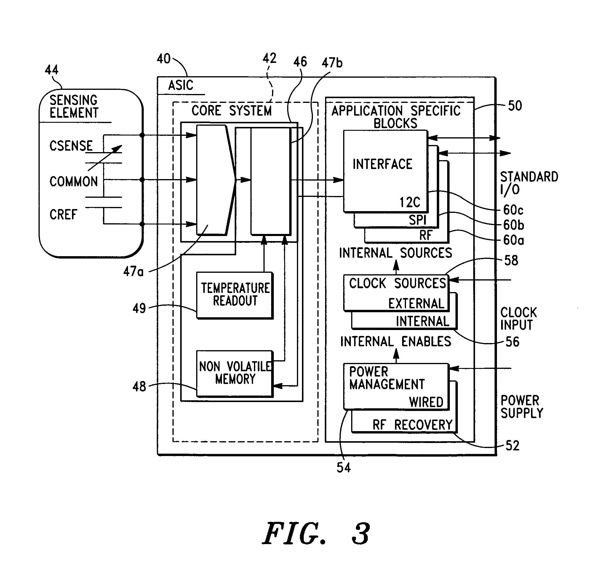
An implantable pressure sensor system having a sensor assembly configured and adapted to measure pressure in a volume, the sensor assembly including at least a first MEMS pressure sensor, an application-specific integrated circuit (ASIC) having memory means, temperature compensation system, drift compensation system, and power supply means for powering the sensor assembly, the first MEMS pressure sensor having a pressure sensing element that is responsive to exposed pressure, the pressure sensing element being adapted to generate a pressure sensor signal representative of the exposed pressure, the temperature compensation system being adapted to correct for temperature induced variations in the pressure sensor signal, the drift compensation system being adapted to correct for pressure and temperature induced pressure sensor signal drift.

Description

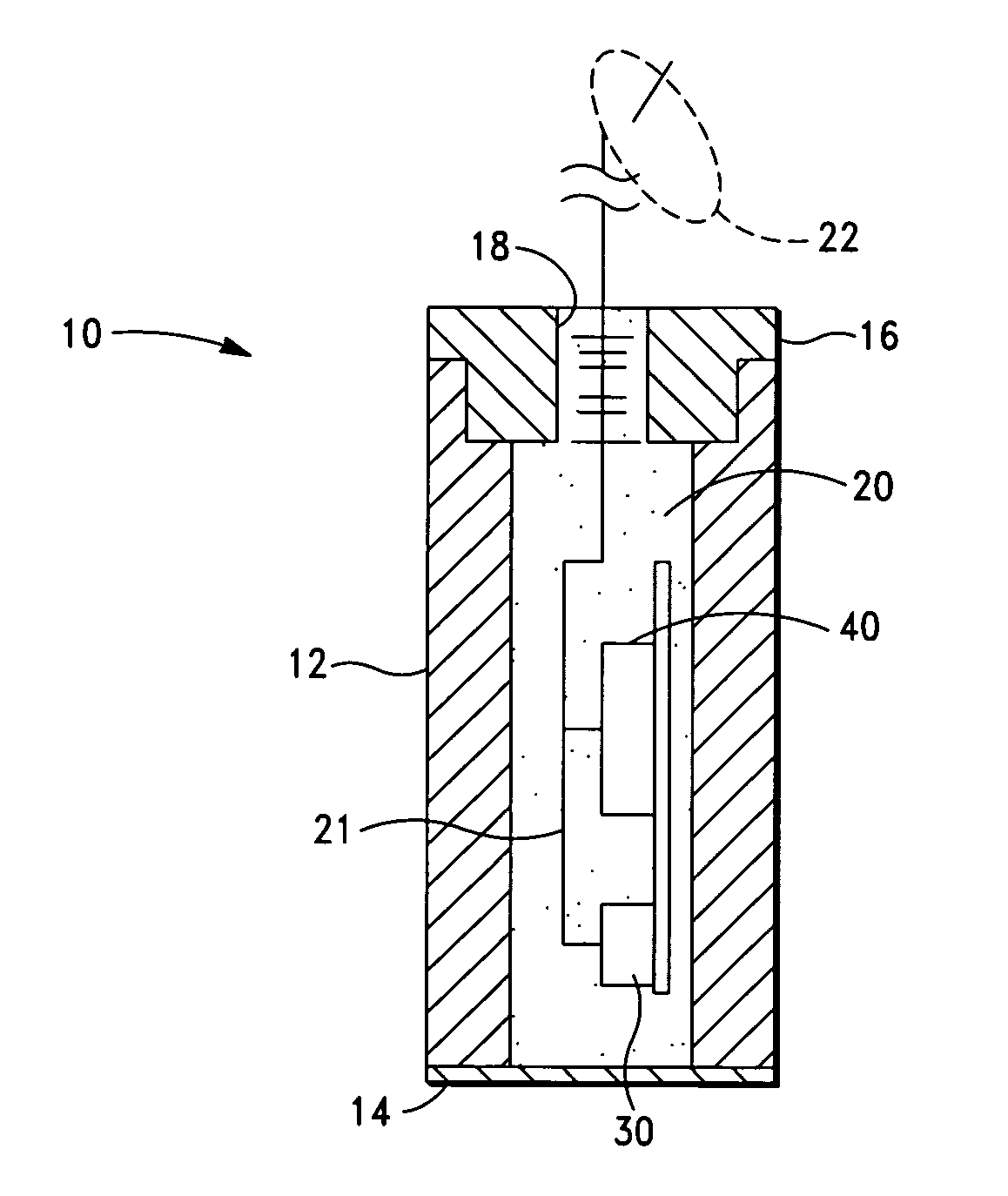
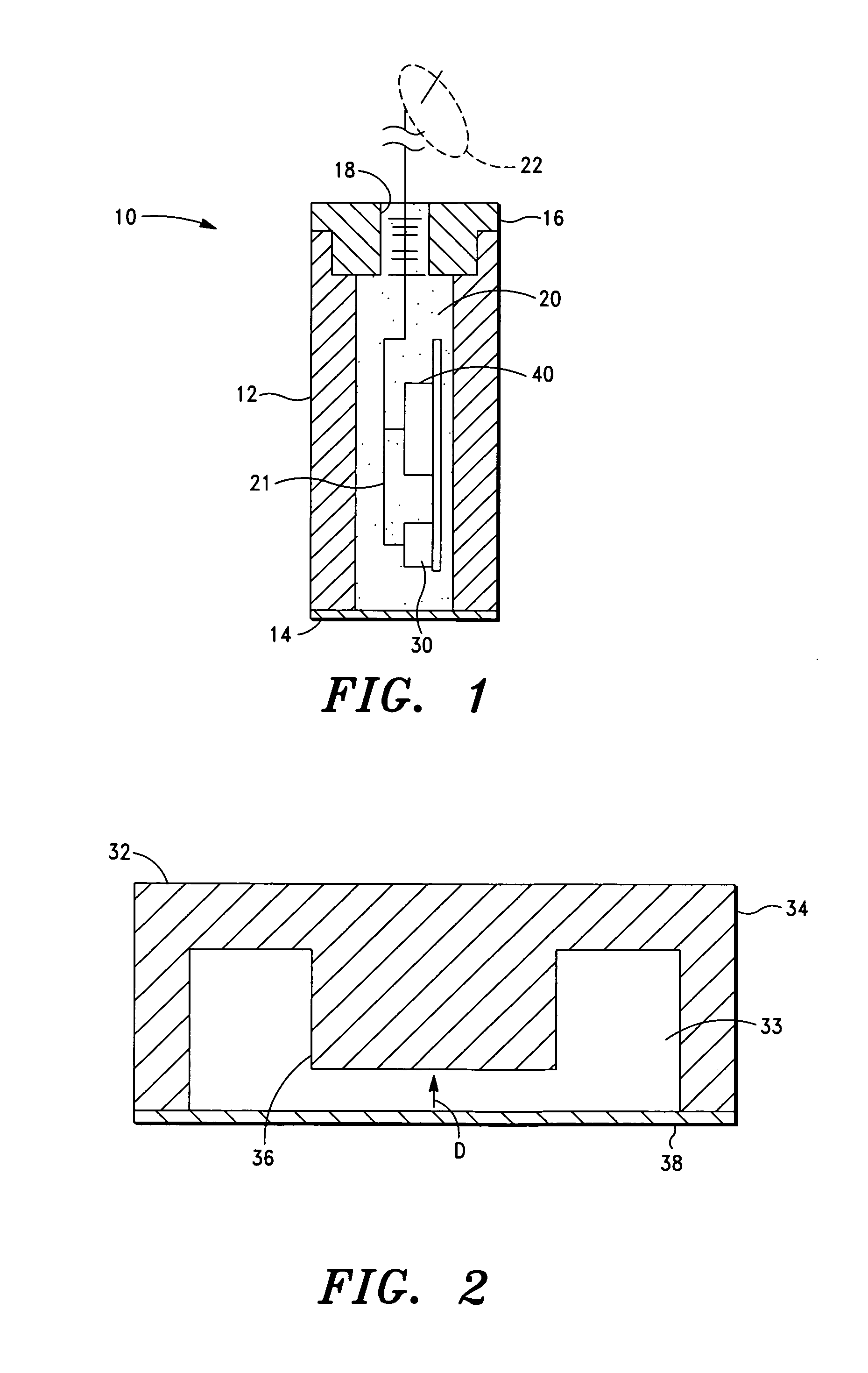
FIELD OF THE PRESENT INVENTION[0001]The present invention relates generally to apparatus and methods for measuring pressure within a cavity. More particularly, but not by way of limitation, the invention relates to apparatus, systems and methods for measuring pressure within a cavity of a subject.BACKGROUND OF THE INVENTION[0002]In medical diagnosis and treatment of a subject or patient, it is often necessary to measure the pressure within one or more organs or systems in the subject's body. Examples of pertinent pressures include, without limitation, intraocular pressure, intratracheal or respiratory pressure, arterial pressure, and bladder pressure.[0003]As is well known in the art, intraocular pressure is a risk factor for the development and progression of glaucoma and other visual impairment conditions. Reduction of intraocular pressure has been shown to reduce the risk of developing glaucoma, as well as the risk of disease progression.[0004]Various conventional systems and met...

Claims


Application Information

Patent Timeline
IPC IPC(8): A61B3/16G01L19/04G01L9/12A61B5/00
CPCA61B3/16A61B5/031G01L27/002A61B2562/028G01L9/125A61B2560/0252
Inventor STONE, ROBERT T.
Owner TRONICS NORTH AMERICA
Why Eureka
Try Eureka