Exhaust gas purification apparatus for engine

a technology of exhaust gas purification apparatus and exhaust gas, which is applied in the direction of mechanical apparatus, engines, machines/engines, etc., can solve the problems of reducing the purification efficiency of nox, the insufficient diffusion and evaporate the inability to achieve sufficient diffusion and evaporate, so as to facilitate the microparticulation of liquid reducing agent or precursor thereof, the effect of reducing the irregular concentration of reducing agent supplied to the reduction catalytic converter

Inactive Publication Date: 2011-07-07
NISSAN DIESEL MOTOR CO
View PDF3 Cites 4 Cited by
  • Summary
  • Abstract
  • Description
  • Claims
  • Application Information

AI Technical Summary

Benefits of technology

[0009]According to this exhaust gas purification apparatus, by appropriately operating the bubble generation device disposed in the reducing agent supply system running from the reducing agent tank to the injection nozzle, the nano-sized to micro-sized bubbles are mixed into the liquid reducing agent or the precursor thereof injection-supplied from the injection nozzle to the exhaust gas on the exhaust upstream side of the reduction catalytic converter. When the liquid reducing agent or the precursor thereof containing the bubbles is injection-supplied from the injection nozzle, division of the liquid reducing agent or the precursor thereof is facilitated by the bubbles, and the bubbles are radically inflated and burst by a pressure change and a temperature change at the time of injection-supplying, so that microparticulation of the liqu

Problems solved by technology

However, when a grain diameter of the liquid reducing agent or the precursor thereof injection-supplied to the exhaust gas on the exhaust upstream side of the NOx reduction catalytic converter is large, the liquid reducing agent or the precursor t

Method used


Image

  • Exhaust gas purification apparatus for engine
  • Exhaust gas purification apparatus for engine
  • Exhaust gas purification apparatus for engine

Examples


first embodiment

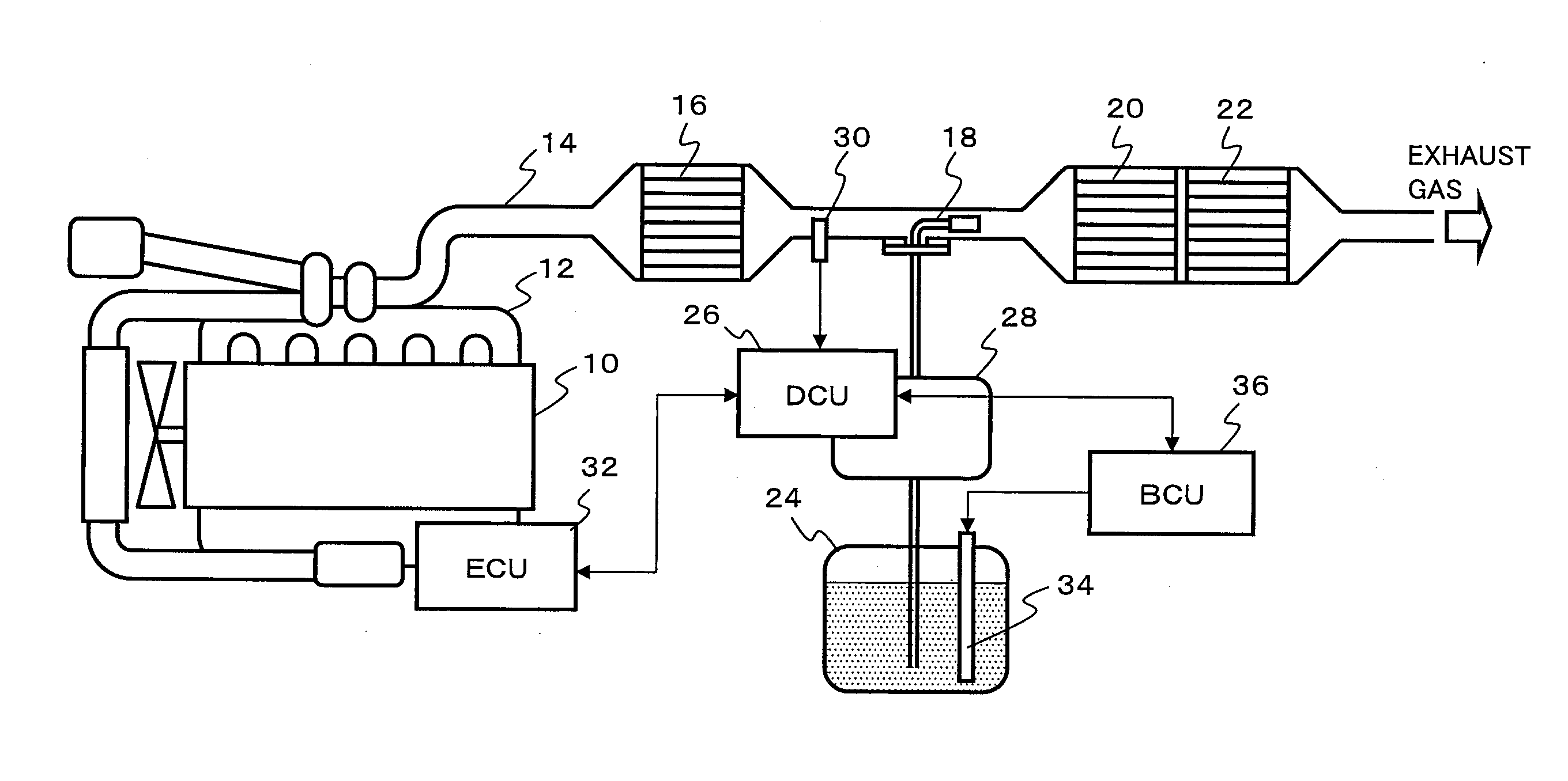
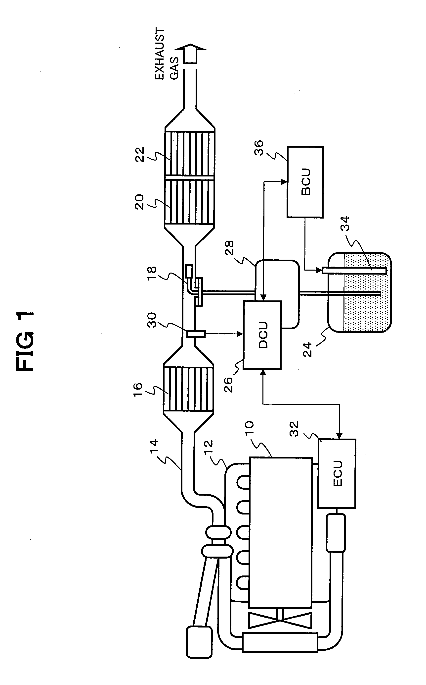
[0020]FIG. 1 illustrates an exhaust gas purification apparatus for selectively reducing and purifying NOx contained in exhaust gas from an engine 10 with using a urea aqueous solution serving as a precursor of a liquid reducing agent.

[0021]In an exhaust pipe 14 (an exhaust passage) connected to an exhaust manifold 12 of the engine 10, in the exhaust flow direction, there is disposed: a nitrogen oxidation catalytic converter 16 for oxidizing nitrogen monoxide (NO) to nitrogen dioxide (NO2); an injection nozzle 18 for injection-supplying the urea aqueous solution in a spray state; a NOx reduction catalytic converter 20 for reducing and purifying NOx with using ammonia generated by hydrolyzing the urea aqueous solution; and an ammonia oxidation catalytic converter 22 for oxidizing ammonia passing through the NOx reduction catalytic converter 20 in this order.

[0022]The urea aqueous solution stored in a reducing agent tank 24 is supplied to the injection nozzle 18 via a reducing agent do...

third embodiment

[0048]FIG. 9 illustrates the exhaust gas purification apparatus for selectively reducing and purifying NOx contained in the exhaust gas from the engine with using the urea aqueous solution serving as the precursor of the liquid reducing agent.

[0049]In the present embodiment, the bubble generation device 34 is disposed (built) not in the reducing agent tank 24 but in the injection nozzle.

[0050]In this manner, the nano-bubbles are only required to be mixed into the urea aqueous solution of which flow rate is controlled by the reducing agent dosing device 28, and there is no need for correcting the dosing flow rate of the urea aqueous solution, so that control can be simplified. It should be noted that in the present embodiment, since the urea aqueous solution passes through the bubble generation device 34 for extremely short time, there is no need for maintaining the bubble mixing ratio X within the predetermined range or to the predetermined value.

[0051]The bubbles mixed into the ure...


PUM


Abstract

In an exhaust gas purification apparatus for an engine includes a bubble generation device, the bubble generation device for mixing nano-sized to micro-sized bubbles into a liquid reducing agent or a precursor thereof injection-supplied from an injection nozzle is disposed in a reducing agent supply system running from a reducing agent tank to the injection nozzle. When the liquid reducing agent or the precursor thereof is injection-supplied from the injection nozzle, the liquid reducing agent or the precursor thereof is divided by bubbles, and the bubbles are radically inflated and burst by a pressure change and a temperature change at the time of injection-supplying, so that microparticulation of the liquid reducing agent or the precursor thereof is facilitated.

Description

[0001]This application is a continuation of PCT / JP2009 / 066133, filed on Sep. 16, 2009.BACKGROUND OF THE INVENTION[0002]1. Field of the Invention[0003]The present invention relates to an exhaust gas purification apparatus for an engine for reducing and purifying nitrogen oxides (NOx) contained in exhaust gas from an engine.[0004]2. Description of Related Art[0005]An exhaust gas purification apparatus disclosed in Japanese Laid-Open (Kokai) Patent Application Publication No. 2003-293740 is proposed as a catalyst purification system for purifying NOx contained in exhaust gas from an engine. This exhaust gas purification apparatus injection-supplies a liquid reducing agent or a precursor thereof at a flow rate in accordance with an engine operation state to exhaust gas on an exhaust upstream side of a NOx reduction catalytic converter disposed in an exhaust passage, so that NOx is subjected to selective reduction reaction with the reducing agent in the NOx reduction catalytic converter....

Claims


Application Information

Patent Timeline
IPC IPC(8): F01N3/18
CPCF01N3/106F01N3/2066F01N3/36F01N13/009F01N2610/14Y02T10/24F01N2610/08Y02T10/12
Inventor YANO, MASAKAZUHIRATA, KIMINOBUMASAKI, NOBUHIKO
Owner NISSAN DIESEL MOTOR CO
Why Eureka
Try Eureka