Construction machine with cab noise reduction device

a construction machine and noise reduction technology, applied in the field of construction machines, can solve the problems of deteriorating ride quality and comfort of the cab, reducing air-conditioning efficiency, and 3 being incapable of suppressing so as to reduce the intrusion of noise into the cab, reduce the noise, and reduce the effect of noise intruding

Inactive Publication Date: 2011-07-07
KOBE STEEL LTD +1
View PDF14 Cites 4 Cited by
  • Summary
  • Abstract
  • Description
  • Claims
  • Application Information

AI Technical Summary

Benefits of technology

[0018]It is an object of the present invention to provide a construction machine comprising a cab noise reduction device capable of effectively reducing noise intruding into a cab, without involving deterioration in ride quality, comfort and air-conditioning efficiency in the cab. This construction machine comprises: a lower propelling body; an upper slewing body including an upper frame and slewably mounted on the lower propelling body; a cab including a floor plate and being installed on the upper frame; and a cab noise reduction device. The cab noise reduction device comprises: the floor plate; an under-cab member which includes a cab deck supporting the cab and is provided under the cab to thereby define a closed-form under-cab space whose periphery is substantially closed, in cooperation with the floor plate; and a resonator which is provided in the under-cab space and reduces noise intruding into the under-cab space, by a resonance effect.

Problems solved by technology

The above publicly known techniques, however, have the following problems.
The technique described in the Patent Document 1 involves a reduction in the real height of the internal space of the cab, which deteriorates ride quality and comfort of the cab.
The technique described in the Patent Document 2 involves that the sound release hole for positively communicating between an inside and an outside of the cab would lower air-conditioning efficiency.
The technique described in the Patent Document 3 is incapable of suppressing the intrusion of noise into a cab.

Method used


Image

  • Construction machine with cab noise reduction device
  • Construction machine with cab noise reduction device
  • Construction machine with cab noise reduction device

Examples


first embodiment

[0043]The first embodiment will be described while assigning the same reference number or code as that in FIGS. 14 to 17 to the same element or component as that shown in FIGS. 14 to 17, as well as those described in the A to D, and omitting its duplicated description.

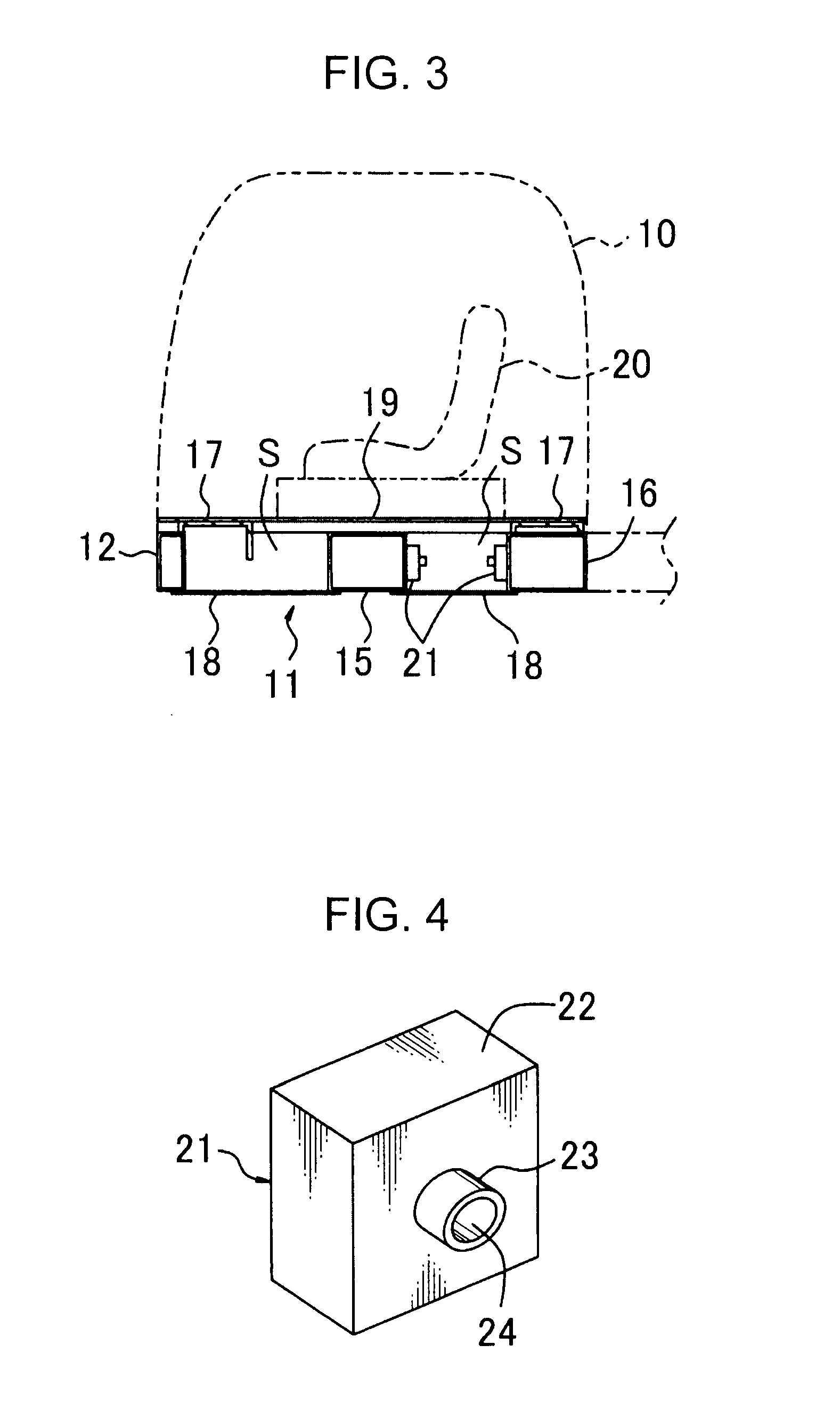
[0044]FIGS. 1 to 7 show a construction machine according to a first embodiment, which machine comprises a cab noise reduction device including a resonator (also called “Helmholtz-type sound absorber”) 21 as shown in FIG. 4. The resonator 21 has a body portion 22, which is a hollow, rectangular parallelepiped-shaped box-like member, and a tubular-shaped neck portion 23. The body portion 22 has a sidewall surrounding an internal space, the sidewall formed with a through-hole at an appropriate position thereof. The neck portion 23 is fixed to the sidewall in such a manner as to surround the through-hole provided in the sidewall of the body portion 22 and protrude outwardly from the sidewall.

[0045]The resonator 21 in the f...

second embodiment

[0051]FIGS. 8 and 9 show the present invention. This embodiment, focusing on a point that each of the front and rear transverse frames 15 and 16 of the cab deck 11 has a widthwisely-long, hollow, box-shaped structure whose periphery is substantially closed, includes forming a resonator by utilization of each of the transverse frames 15 and 16.

[0052]In FIGS. 8 and 9, shown is only the front transverse frame 15 representatively, in the two transverse frames 15 and 16. FIG. 8 is a horizontal sectional view of the front transverse frame 15, and FIG. 9 is a diagram (rear view) of the front transverse frame 15, when viewed from the arrowed line IX in FIG. 8.

[0053]In the second embodiment, since the transverse frame 15 has a volume too large to form a resonator, there are provided a plurality of (in the illustrated embodiment, four) partition plates 25, - - - inside the transverse frame 15 in side-by-side relation in a longitudinal direction thereof, to thereby define two independent close...

third embodiment

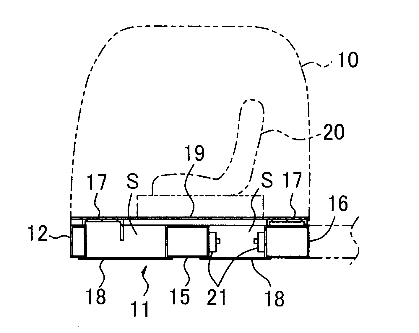
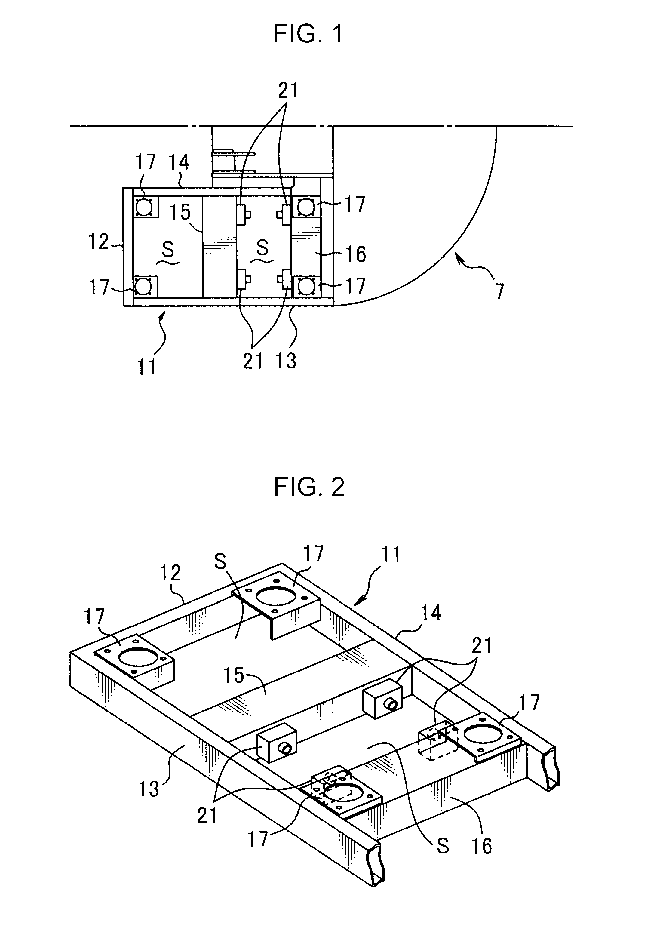
[0056]FIG. 10 shows the present invention. This embodiment includes a vertical partition plate 29, in addition to the partition plates 25, - - - : the vertical partition plate 29 is so provided as to extend in the longitudinal direction of the transverse frame 15, i.e., the rightward-leftward direction of the hydraulic shovel, in a vertical posture, while intersecting with the partition plates 25, - - - at a right angle, thereby further partitioning each of the closed spaces 26 and 26 into a front space 26a and a rear space 26b. In association with the respective partitioned spaces, a plurality of openings 27 each opened in the frontward-rearward direction are provided; thus a plurality of resonators 30, - - - are formed. These resonators 30, - - - are capable of lowering sound pressures in both of the two under-cab spaces S and S defined on the front and rear sides of the transverse frame 15 as shown in FIGS. 1 to 3.


PUM


Abstract

A construction machine capable of effectively reducing noise which would intrude into a cab, without deterioration in ride quality, comfort and air-conditioning efficiency in the cab is provided. The construction machine includes a lower propelling body, an upper slewing body including an upper frame, a cab including a floor plate and installed on the upper frame, and a cab noise reduction device. The cab noise reduction device includes: the floor plate; an under-cab member including a cab deck supporting the cab and provided under the cab to define a closed-form under-cab space whose periphery is substantially closed, in cooperation with the floor plate; and a resonator reducing noise in the under-cab space by a resonance effect.

Description

TECHNICAL FIELD[0001]The present invention relates to a construction machine, such as a hydraulic shovel, which comprises a cab and a cab noise reduction device for suppressing the intrusion of noise into the cab.BACKGROUND ART[0002]The background art of the present invention will be described by taking a hydraulic shovel as an example.[0003]FIG. 14 shows a hydraulic shovel which is a conventional construction machine. This hydraulic shovel comprises a crawler type lower propelling body 1, an upper slewing body 2 mounted on the lower propelling body 1 slewably about a vertical axis thereof, and an attachment 6 attached to the upper slewing body 2, wherein the attachment 6 includes a boom 3, an arm 4 and a bucket 5.[0004]The upper slewing body 2 includes an upper frame 7 as a base, which has a rear portion on which an engine room 9 for accommodating an engine 8 therein is provided, and a front portion on which a cab 10 is installed to allow an operator to perform various operations t...

Claims


Application Information

Patent Timeline
Patent Type & Authority Applications(United States)
IPC IPC(8): G10K11/172
CPCB60R13/0815B62D33/06E02F9/0858E02F9/163G10K11/172B62D33/0604
Inventor MASUDA, KYOKOKIMURA, YASUMASAUEDA, KAZUHIRO
Owner KOBE STEEL LTD
Why Eureka
Try Eureka