Method for Soldering Contact Wires to Solar Cells

Inactive Publication Date: 2011-07-07
SCHMID TECH SYST
View PDF11 Cites 15 Cited by
  • Summary
  • Abstract
  • Description
  • Claims
  • Application Information

AI Technical Summary

Benefits of technology

[0006]The invention is based on the object of providing an above-mentioned method by means of which disadvantages of the prior art can be avoided and, in particular, mechanical stresses in the solar cell as a result of the preheating or the soldering operation itself can be reduced as far as possible or even completely eliminated.

Problems solved by technology

The required preheating of the cell, under certain circumstances almost up to the liquidus temperature of the soldering tin, and the subsequently soldering operation can bring about a fracture of the solar cell in an unfavourable case, particularly if said cell is already weakened by microcracks.

Method used


Image

  • Method for Soldering Contact Wires to Solar Cells
  • Method for Soldering Contact Wires to Solar Cells
  • Method for Soldering Contact Wires to Solar Cells

Examples


Embodiment Construction

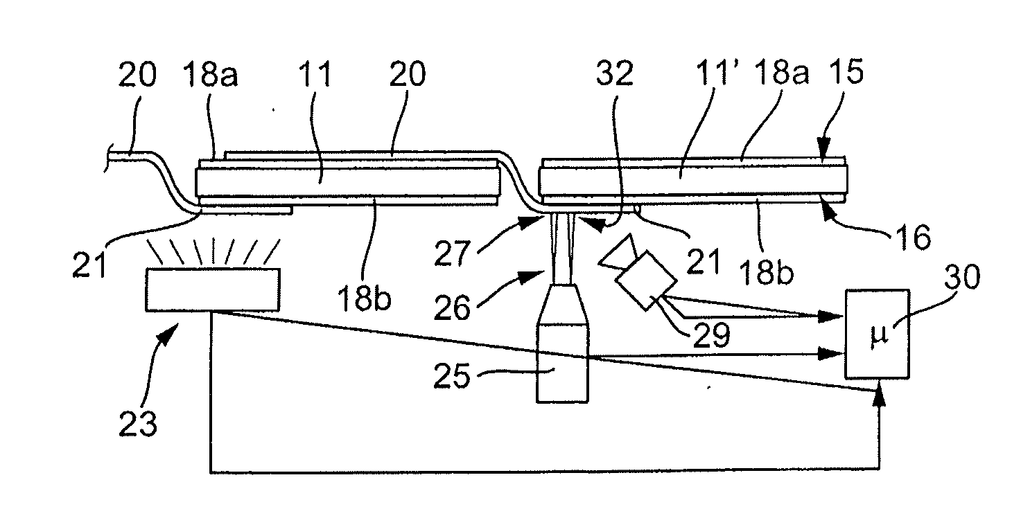
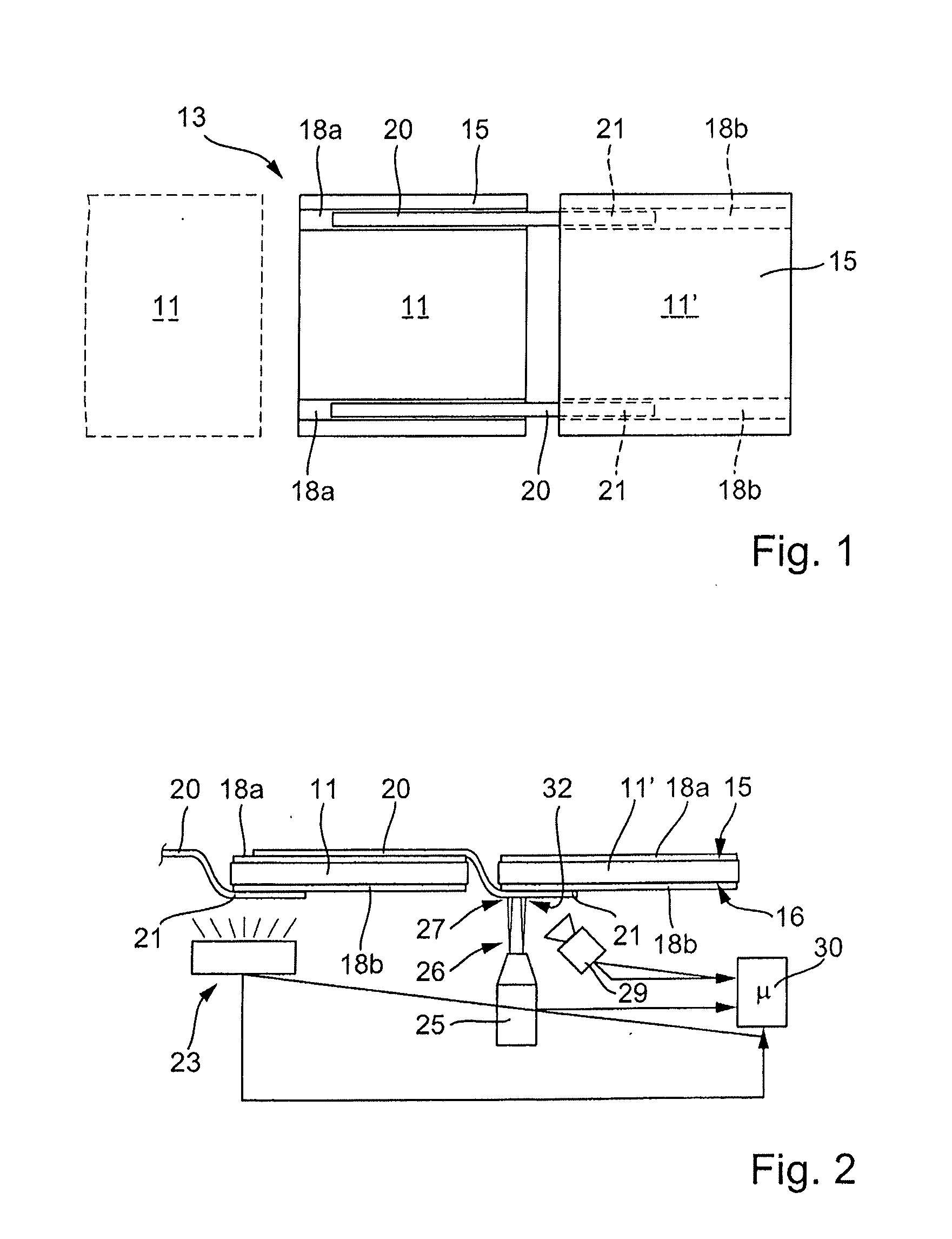
[0026]FIG. 1 illustrates in plan view a first solar cell 11 and on the right alongside the latter a second solar cell 11′. These two solar cells 11 and 11′, possibly also with further solar cells (not illustrated) already connected or yet to be connected, are formed as a chain 13 or so-called stringer. A completely interconnected solar module is produced from a plurality of such chains 13 in parallel with one another, as is known per se. In conjunction with FIG. 2 it can be seen that the solar cells 11 and 11′ have a top side 15 and an underside 16.

[0027]The top side 15 bears two narrow strip-shaped contact regions 18a, which are produced in a conventional manner by a metal coating on the solar cell. There can also be three of such contact regions. Corresponding metal-coated contact regions 18b are provided on the underside 16, said contact regions likewise running over the entire length of the solar cell 11 and 11′.

[0028]The solar cells 11 and 11′ are at a distance of a few millime...


PUM

PropertyMeasurementUnit
Temperatureaaaaaaaaaa
Fractionaaaaaaaaaa
Fractionaaaaaaaaaa

Abstract

In a method for soldering contact wires to a side of a solar cell for producing the electrical contact-making, the solar cells have at least one metallic strip-shaped region. A contact wire is soldered onto the latter for the electrical connection of the solar cell, wherein the soldering duration or the duration of the energy input externally onto the soldering region is very short and is less than 800 ms.

Description

CROSS-REFERENCE TO RELATED APPLICATIONS[0001]This application is a continuation of PCT Application No. PCT / EP2009 / 006268, filed Aug. 28, 2009, and claims priority to DE 10 2008 046 330.2 filed Aug. 29, 2008, the disclosures of which are hereby incorporated by reference in their entirety.FIELD OF APPLICATION AND PRIOR ART[0002]The invention relates to a method for soldering contact wires to a solar cell such as is carried out in particular during the assembly together with electrical interconnection of a plurality of solar cells to form a composite assembly or a module.[0003]In photovoltaics, the trend in technological development is constantly toward lowering costs and increasing the efficiency. During the electrical connection of solar cells to form a solar module, chains or so-called stringers are predominantly used. In said stringers, the cells are soldered with contact wires to form stringers by means of a soldering process. Contact soldering is predominantly used during this so...

Claims


Application Information

Patent Timeline
IPC IPC(8): B23K1/002B23K31/12B23K1/20B23K26/00
CPCB23K1/0016B23K1/0056H01L2224/45147B23K2201/38H01L24/85H01L31/188H01L2224/48H01L2224/85H01L2924/01004H01L2924/01029H01L2924/0105H01L2924/01077H01L2924/01082Y02E10/50H01L2924/01006H01L2924/01033H01L2924/01068H01L2924/014H01L2924/00H01L2224/45015H01L2924/12042H01L24/45H01L24/48B23K2101/38H01L2924/00014
Inventor KALMBACH, JENSMULLER, PATRIKKLINGEBIEL, GERHARD
Owner SCHMID TECH SYST
Why Eureka
Try Eureka