Magnetic testing method and magnetic testing apparatus

a testing method and magnetic technology, applied in the field of magnetic testing methods and magnetic testing apparatuses, can solve the problems of lowering the s/n ratio of fault detection, not being able to estimate the angle information of the flaw, and not being able to use the phase analysis method

Active Publication Date: 2011-07-07
NIPPON STEEL CORP
View PDF2 Cites 13 Cited by
  • Summary
  • Abstract
  • Description
  • Claims
  • Application Information

AI Technical Summary

Benefits of technology

[0029]The present invention has been devised to solve the problems of the related art, and an object of the present invention is to provide a magnetic testing method and a magnetic testing apparatus which can precisely detect flaws existing in a material to be tested and extending in various directions by using a rotating magnetic field.
[0032]Further, in accordance with the present invention, the candidate flaw signal is extracted by synchronously detecting the testing signal by using the first current as the reference signal and thereafter synchronously detecting by using the second current as the reference signal. In other words, since the testing signal is synchronously detected at the first setout by using the first current having the higher frequency than the rotating frequency (corresponding to the frequency of the second current) of the magnetic field as the reference signal, it is easy to bring the cycle component included in the flaw signal obtained from the position at which the flaw actually exists into line with the cycle of the reference signal, in comparison with the conventional case of synchronously detecting based on the reference signal having the same frequency as the rotating frequency of the magnetic field, and there can be expected that it is possible to sufficiently obtain the effect (extracting the flaw signal from the testing signal at the high S / N ratio) of the synchronous detection. Further, since the phase information of the flaw signal included in the smoothened testing signal tends to be held even by smoothening the testing signal extracted by synchronously detecting by using the first current as the reference signal per unit region corresponding to about two or three cycles of the reference signal, it is possible to estimate the angle information of the flaw (what direction the flaw extends in). Further, since the phase information of the flaw signal tends to be held even by smoothening as mentioned above, it is possible to apply the phase analysis method at a time of synchronously detecting successively by using the second current as the reference signal, and it is possible to suppress the influence of the liftoff varying noise or the like applied to the flaw detection performance.
[0033]Further, in accordance with the present invention, there is displayed the testing image constructed by a plurality of pixels corresponding to the respective positions of the material to be tested. Each of the pixels has the gray level corresponding to the intensity of the candidate flaw signal (the testing signal after synchronously detecting by using the second current as the reference signal) at each of the positions (including the case that the intensity of the candidate flaw signal is binarized by the predetermined threshold value). The phase of the candidate flaw signal at each of the positions can be identified in the teting image. Specifically, for example, one color image is displayed as the testing image, the color image being structured such that the pixels are colored into the different colors in correspondence to the phase of the candidate flaw signal obtained by applying the phase analysis method (the gray level of each of the pixels is different in correspondence to the intensity of the candidate flaw signal). Alternatively, a plurality of gray images in which the phase (the range of phase) of the candidate flaw signal included in each of the images is different (the gray level of each of the pixels is different in correspondence to the intensity of the candidate flaw signal) are displayed as the testing image. Accordingly, since it is possible to visual observe the phase (the angle information) in addition to the intensity of the candidate flaw signal in the testing image, it is possible to accurately evaluate the continuity of the flaw.
[0035]In accordance with the invention as mentioned above, it is possible to expect that the effect of the synchronous detection can be sufficiently obtained, in the same manner as mentioned above, to estimate the angle information of the flaw, and to suppress the influence of the liftoff varying noise or the like with respect to the flaw detection performance. Further, it is possible to automatically and accurately evaluate the continuity of the flaw in accordance with the image processing.
[0041]In accordance with the present invention, it is possible to solve the problems (1) to (4) mentioned above, and to precisely detect the flaws extending in the various directions and existing in the material to be tested, by using the rotating magnetic field.

Problems solved by technology

However, the conventional magnetic testing method utilizing the rotating magnetic field has the following problems due to using the exciting current having the single frequency.
(1) Since it is not possible to sufficiently obtain the effect of the synchronous detection, there is a risk that the flaw detection performance (S / N ratio) is lowered.
(2) It is not possible to estimate an angle information of the flaw (what direction the flaw extends in).
(3) It is not possible to use the phase analysis method which is general as a method of improving the flaw detection performance (S / N ratio) in the eddy current testing method.
(4) It is not possible to accurately evaluate a continuity of the flaw.
Therefore, in accordance with the conventional magnetic testing method utilizing the rotating magnetic field, it is possible to conceptually detect the flaws extending in the various directions, however, it cannot be said that the flaw detection performance is practically sufficient.
Further, since it is not possible to estimate the angle information of the flaw, it is hard to determine a cause by which the flaw is generated.
In other words, since the cycle of the flaw signal does not coincide with the cycle of the reference signal, it is not possible to sufficiently obtain the effect of the synchronous detection (the effect of extracting the flaw signal from the testing signal at the high S / N ratio), and there is a risk that the flaw detection performance is lowered (the problem (1) mentioned above).
Further, since the phase information of the flaw signal after smoothening is lost as mentioned above, and it is not possible to specify what position the flaw signal exists in one cycle of the exciting current, it is necessary to always evaluate based on the ratio between the amplitude of the flaw signal and the amplitude of the noise as mentioned above with reference to FIG. 3A, at a time of evaluating the flaw detection performance (S / N ratio).
However, in the conventional magnetic testing method utilizing the rotating magnetic field, since it is not possible to estimate the angle information of the flaw as mentioned above, it is necessary to form the testing image based on only the amplitude information of the testing signal.
Accordingly, with regard to the flaw which is detected in the segmented manner, for example, due to a partial small depth of the flaw in spite that the flaw is actually constituted by a single continuous flaw, and is displayed in the segmented manner in the testing image, it is hard to accurately evaluate the continuity of the flaw (the problem (4) mentioned above).
Particularly, in the case that position resolution of the testing image cannot help lowering (common case from a restriction of a detection efficiency in the line feeding the material to be tested at a high speed), since it is not possible to set a scanning interval of a detection sensor which is sufficiently small in comparison with a dimension of the flaw, it is not possible to obtain an accurate information what direction the flaw extends, based on the testing image itself.
Accordingly, it is hard to accurately evaluate the continuity of the flaw.
Accordingly, there is a risk that the harmfulness of the flaw cannot be accurately evaluated.

Method used


Image

  • Magnetic testing method and magnetic testing apparatus
  • Magnetic testing method and magnetic testing apparatus
  • Magnetic testing method and magnetic testing apparatus

Examples


Embodiment Construction

[0059]A description will be given below of an embodiment in accordance with the present invention appropriately with reference to the accompanying drawings.

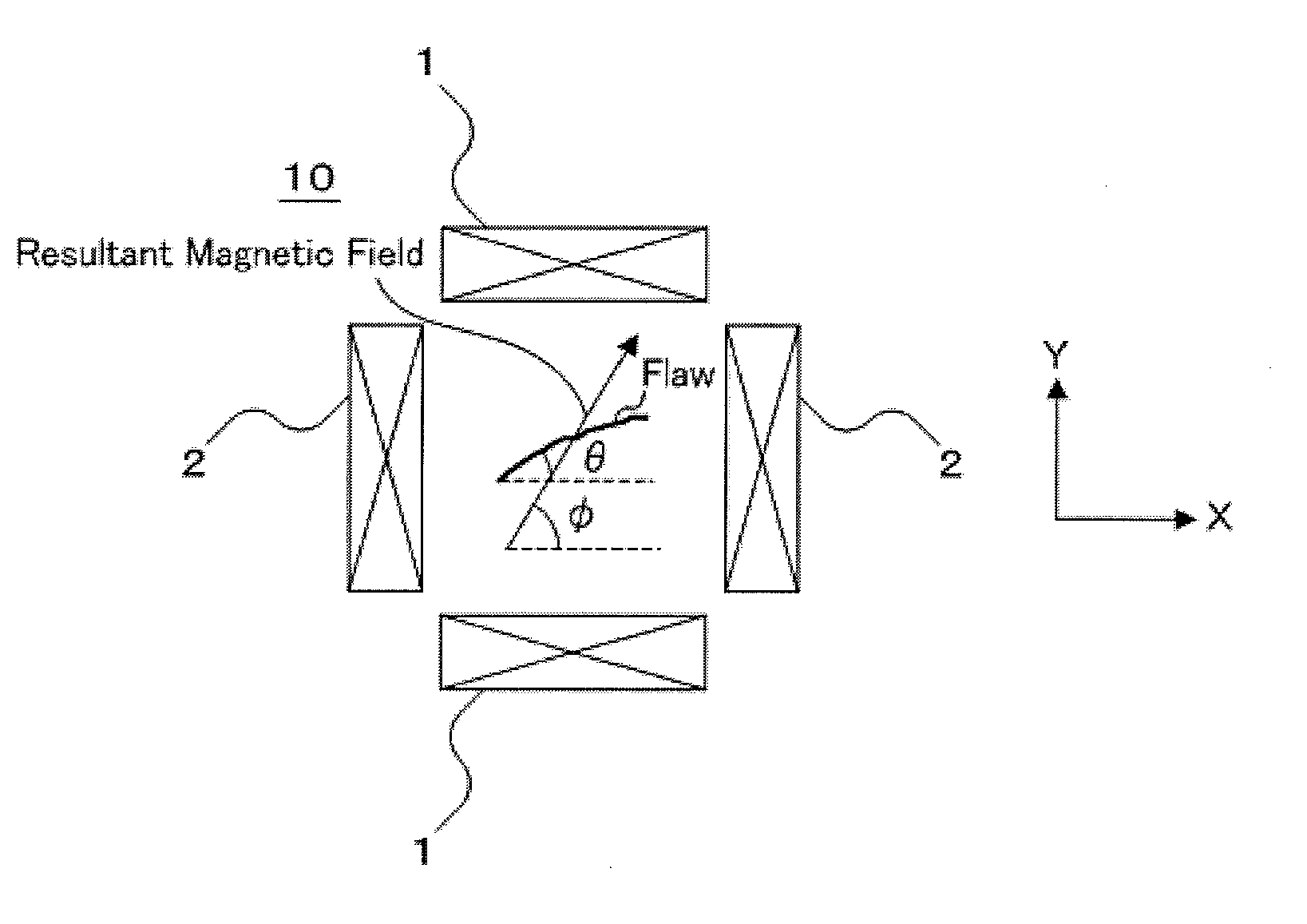
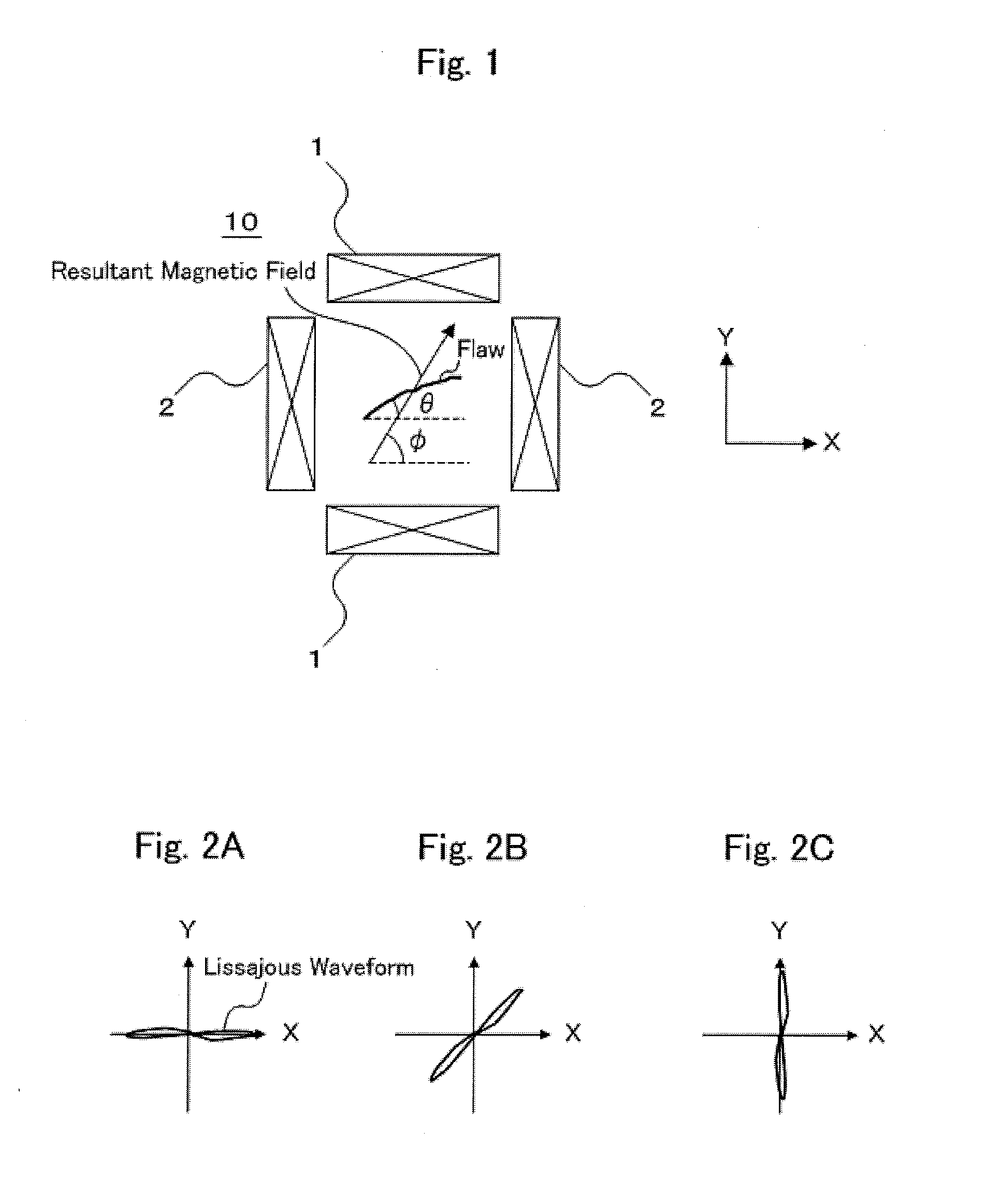
[0060]FIG. 9 is a block diagram showing a schematic configuration of a magnetic testing apparatus in accordance with an embodiment of the present invention. FIG. 10 shows a schematic outer appearance view of a testing probe shown in FIG. 9. As shown in FIG. 9, a magnetic testing apparatus 100 in accordance with the present embodiment is provided with a magnetizing device 1 applying a rotating magnetic field to a material to be tested, a detecting device 2 detecting a testing signal generated by the rotating magnetic field, and a signal processing device 3 applying a signal processing to the testing signal.

[0061]The magnetizing device 1 is provided with an exciting coil 11 applying an exciting current for generating the rotating magnetic field. As shown in FIG. 10, the exciting coil 11 is provided with an X-direction exciting coil...


PUM

PropertyMeasurementUnit
angleaaaaaaaaaa
angleaaaaaaaaaa
angleaaaaaaaaaa

Abstract

A magnetic testing apparatus has a magnetizing device applying a rotating magnetic field to a material to be tested, a testing signal detecting device, and a signal processing device applying signal processing to the testing signal. The signal processing device has a first synchronous detecting device detecting a testing signal by using the first current as a reference signal, a second synchronous detecting device detecting an output signal of the first synchronous detecting device by using the second current as a reference signal to extract a candidate flaw signal, and a testing image display device displaying a testing image in which each of pixels has a gray level corresponding to an intensity of the candidate flaw signal at each of positions of the material to be tested, and a phase of the candidate flaw signal at each of the positions is capable of being identified.

Description

BACKGROUND OF THE INVENTION[0001]1. Field of the Invention[0002]The present invention relates to a magnetic testing method and a magnetic testing apparatus which can detect flaws existing in a material to be tested and extending in various directions with high precision by using a rotating magnetic field.[0003]2. Description of the Related Art[0004]Conventionally, as a method of detecting a flaw existing in a material to be tested such as a steel plate, a steel pipe or tube or the like in a nondestructive manner, there have been known magnetic testing methods such as an eddy current testing method, a magnetic flux leakage testing method and the like. The eddy current testing method is a testing method utilizing a fact that an eddy current induced by applying an alternating magnetic field to a material to be tested is disturbed by the flaw. Further, the magnetic flux leakage testing method is a testing method utilizing a fact that in the case that a magnetic field is applied to a mat...

Claims


Application Information

Patent Timeline
Patent Type & Authority Applications(United States)
IPC IPC(8): G01N27/82
CPCG01N27/9046G01N27/9013
Inventor SUZUMA, TOSHIYUKIIMANISHI, KENJI
Owner NIPPON STEEL CORP
Why Eureka
Try Eureka