Open loop load pull arrangement with determination of injections signals

a technology of injection signal and load pull, which is applied in the direction of electronic circuit testing, measurement devices, instruments, etc., can solve the problems of inapplicability to wideband modulated signals, unpractical arrangement, and limited dynamic range of proposed arrangement, so as to achieve a wide range of application

Active Publication Date: 2011-07-07
ANTEVERTA MW
View PDF6 Cites 20 Cited by
  • Summary
  • Abstract
  • Description
  • Claims
  • Application Information

AI Technical Summary

Benefits of technology

[0006]The present invention seeks to provide an improved load pull measurement arrangement and method, which allows a broader application range (higher frequencies, more broadband, wideband multi-tone).

Problems solved by technology

This approach can be used only with single tone input stimulus to the device under test and is not suitable for wideband modulated signals.
However, for wideband modulated signals, this arrangement is not practical.
Also the dynamic range of the proposed arrangement will be very limited.

Method used


Image

  • Open loop load pull arrangement with determination of injections signals
  • Open loop load pull arrangement with determination of injections signals
  • Open loop load pull arrangement with determination of injections signals

Examples


examples

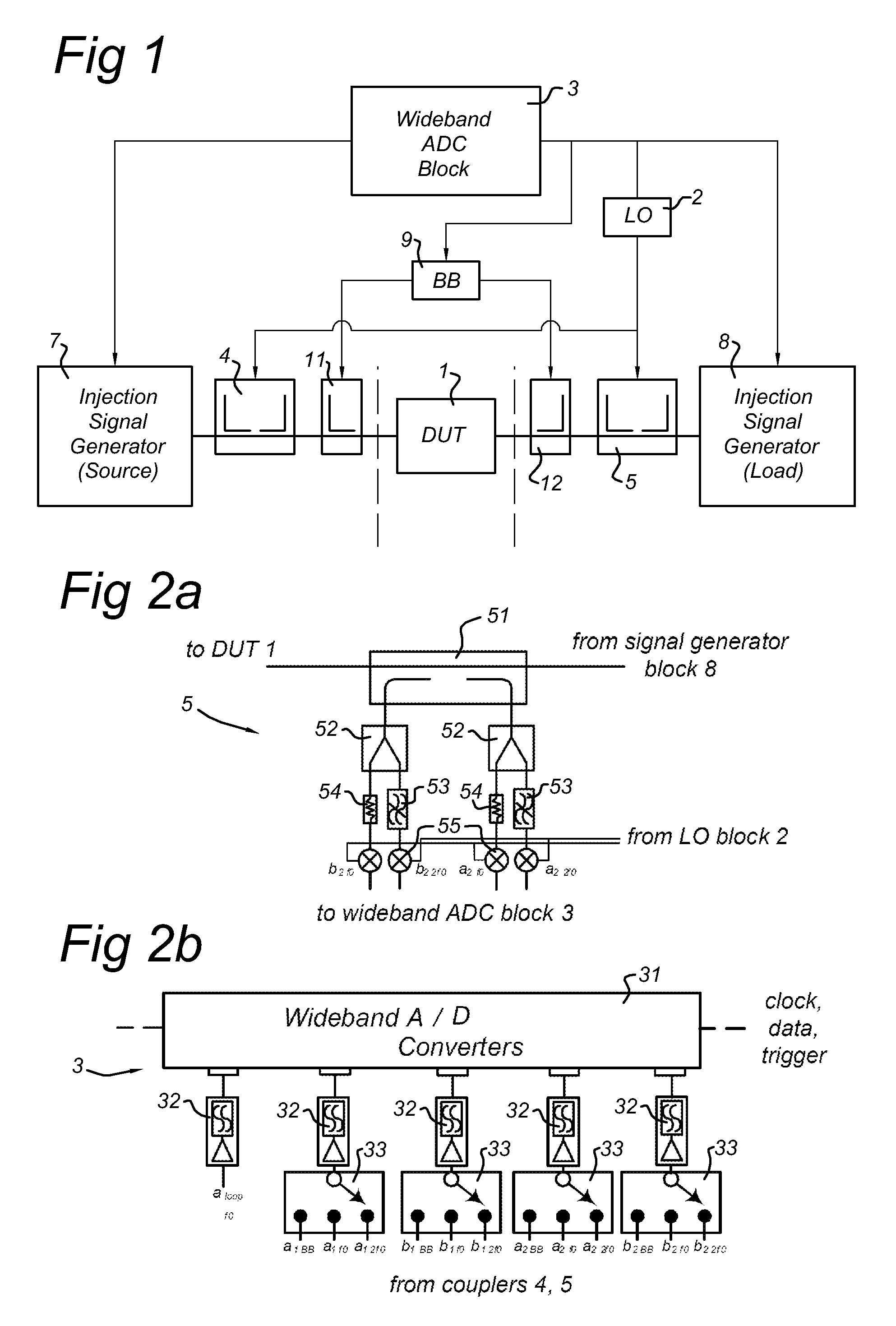
[0092]The functionality of such a load-pull characterization system is demonstrated in FIGS. 5a and 5b which show the uncorrected (a) and corrected (b) reflection coefficient offered to the device under test 1 output for a 14 tone input signal with 15 MHz bandwidth in the form of Smith-charts. Both the input signal, as well the injection signals are generated using the synchronized AWG's 81, which use the same clock and data record length to store the waveforms. All signals are coherently up-converted as described with respect to FIG. 2c. In FIG. 8 a spectral diagram is shown of this 14 tone input signal, centered at 2.14 GHz. FIG. 5a shows measured reflection coefficient of 14 frequency tones in the proposed active load pull system over a frequency bandwidth of 15 MHz, when no compensation is present for the electrical delay and gain variation in the load pull system over this frequency range. So in this case the injection signals are not found by optimization for each tone, but se...


PUM


Abstract

Measurement arrangement and method for active load pull measurements of a device under test (1). A wideband analog-to-digital conversion block (3) is provided for obtaining measurement data. First and second injection signal generators (7, 8) are connected to a source side and a load side of the device under test (1). This set up allows to create predetermined reflection coefficients at reference planes of the device under test (1). Injection signal parameters as determined are converted into the injection signals at the source and load side by digital-to-analog conversion. The wideband analog-to-digital conversion block (3) is further arranged for analog-to-digital conversion of the intermediate frequency signals to obtain the actual measured reflection coefficient versus frequency functions with a first frequency resolution. The first frequency resolution applied in the analog-to-digital conversion is equal to or better than a second frequency resolution applied in the digital-to-analog conversion.

Description

FIELD OF THE INVENTION[0001]The present invention relates to an open-loop load-pull measurement approach which facilitates the full control and measurement of the reflection coefficients offered to a device under test (DUT) at base band, fundamental and harmonic frequencies over a large modulation bandwidth.PRIOR ART[0002]American patent publication US2007 / 0194776 discloses a real-time load-pull arrangement which allows setting and measurement of the device reflection coefficients for the fundamental in one shot. This approach can be used only with single tone input stimulus to the device under test and is not suitable for wideband modulated signals.[0003]American patent publication US 2007 / 0182424 discloses an implementation of load control in (closed) feedback loops by making use of frequency down conversion techniques to implement the filter functions at a lower frequency which is easier. However, the proposed solution assumes a time continuous feedback action for the active loop...

Claims


Application Information

Patent Timeline
Patent Type & Authority Applications(United States)
IPC IPC(8): G01R27/28
CPCG01R31/2822G01R27/32
Inventor MARCHETTI, MAUROPELK, MARCO JOHANNESDE VREEDE, LEONARDUS CORNELIS NIICOLAAS
Owner ANTEVERTA MW
Why Eureka
Try Eureka