Moving image coding method, moving image coding apparatus, program, and integrated circuit

a coding method and image technology, applied in the direction of signal generators with optical-mechanical scanning, color televisions with bandwidth reduction, signal generators, etc., can solve the problems of difficult compression of images, inability to handle these massive amounts of information, and inability to send video for a television and a camera, so as to achieve easy compression, prevent subjective degradation of image quality, and improve the effect of image quality

Inactive Publication Date: 2011-07-07
SOVEREIGN PEAK VENTURES LLC
View PDF8 Cites 57 Cited by
  • Summary
  • Abstract
  • Description
  • Claims
  • Application Information

AI Technical Summary

Benefits of technology

[0052]According to the moving image coding method and the moving image coding apparatus in the present invention, even when the degree of difficulty in compressing an input moving image or the target coding bit rate is considerably changed, an image that can be easily compressed at a low bit rate can be prevented from being coded with a larger resolution. As a result, a moving image can be coded without causing any uncomfortable feeling, such as blurs resulting from frequent change in the resolution at a low bit rate. Moreover, the subjective degradation in the image quality can be prevented.

Problems solved by technology

It is therefore not practical to handle these massive amounts of information in digital form on the above information media.
For example, video telephony services are available over Integrated Services Digital Network (ISDN) lines with a transmission speed of 64 Kbit / s to 1.5 Mbit / s, but video for a television and a camera cannot be sent as it is over the ISDN lines.
In contrast, there are images that are very difficult to be compressed due to no correlation between pixels, such as white noise.
However, even when an image having the less number of pixels is enlarged into an image having the larger number of pixels, since it is not possible to achieve the representation over the fineness (minuteness) that can be represented using the less number of pixels that have been coded, the obtained image becomes more blurred than the image that has been coded at the same magnification.

Method used


Image

  • Moving image coding method, moving image coding apparatus, program, and integrated circuit
  • Moving image coding method, moving image coding apparatus, program, and integrated circuit
  • Moving image coding method, moving image coding apparatus, program, and integrated circuit

Examples


embodiment 1

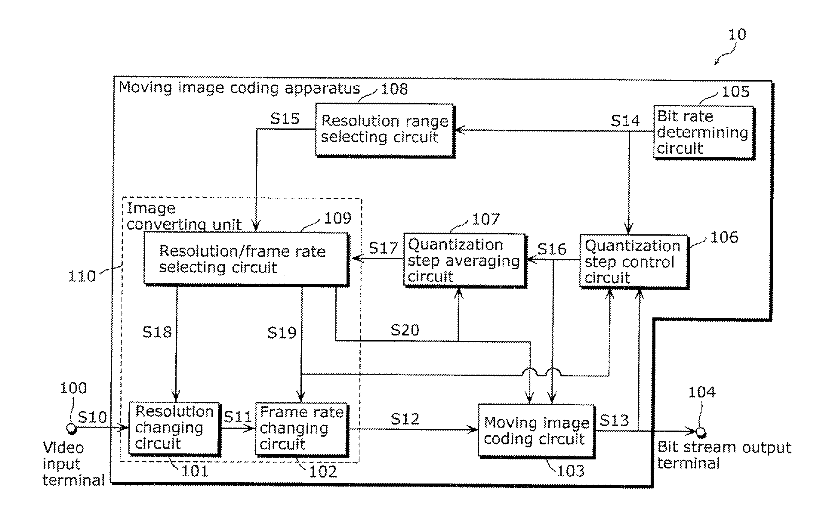
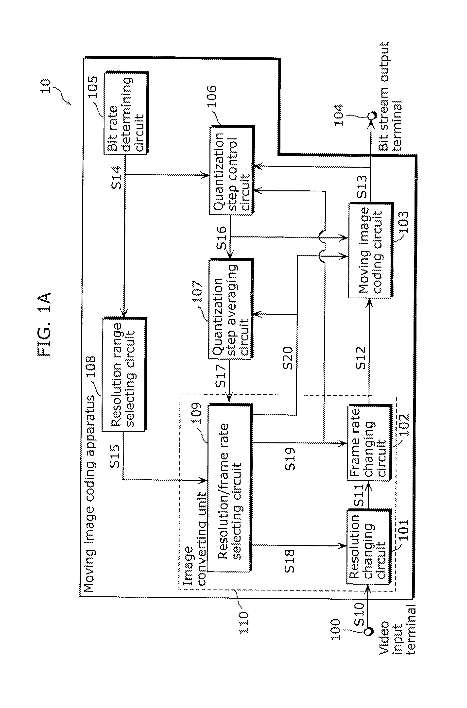
[0083]FIG. 1A is a block diagram of a moving image coding apparatus 10 according to Embodiment 1 in the present invention.

[0084]The moving image coding apparatus 10 includes a resolution changing circuit (resolution changing unit) 101, a frame rate changing circuit (frame rate changing unit) 102, a moving image coding circuit (moving image coding unit) 103, a bit rate determining circuit (bit rate determining unit) 105, a quantization step control circuit (quantization step calculating unit) 106, a quantization step averaging circuit (average value calculating unit) 107, a resolution range selecting circuit (resolution range selecting unit) 108, and a resolution / frame rate selecting circuit (image quality determining unit) 109. The moving image coding apparatus 10 obtains a video signal S10 from a video input terminal 100, and transmits a generated bit stream S13 from a bit stream output terminal 104 through a transmission channel.

[0085]The resolution changing circuit 101 changes th...

embodiment 2

[0183]The present invention may be implemented not only as the moving image coding apparatus 10 and the moving image coding method as described in Embodiment 1 but also as a program causing a computer to execute the moving image coding method according to Embodiment 1.

[0184]FIGS. 15A to 15C illustrate a case where the moving image coding method according to Embodiment 1 is implemented by a computer system using a flexible disk FD on which the moving image coding method is stored.

[0185]FIG. 15 illustrates an example of a physical format of a magnetic disk MD that is a recording medium body. FIG. 15B illustrates a front view and a sectional view of a case F for holding the magnetic disk MD, and the magnetic disk MD. FIG. 15C illustrates a configuration for recording the program on the flexible disk FD and reproducing it from the flexible disk FD.

[0186]The flexible disk FD includes the magnetic disk MD that is the recording medium body, and the case F for holding the magnetic disk MD. ...

embodiment 3

[0191]The program for implementing the configuration of the image coding method according to Embodiments 1 and 2 is recorded on a recording medium, so that the processes described in Embodiments 1 and 2 can be easily implemented by an independent computer system. As long as the program can be recorded, any recording medium may be used, such as a magnetic disk, an optical disc, an optical magnetic disk, an IC card, and a semiconductor memory.

[0192]Hereinafter, the applications to the image coding method described in Embodiments 1 and 2 and a system using the same will be described.

[0193]FIG. 16 illustrates an overall configuration of a content providing system ex100 for implementing content distribution services. The area for providing communication services is divided into cells of desired size, and base stations ex106 to ex110 which are fixed wireless stations are placed in each of the cells.

[0194]The content providing system ex100 is connected to devices, such as a computer ex111,...


PUM


Abstract

The moving image coding method includes: changing at least one of a resolution and a frame rate of an input image, according to a degree of difficulty in coding the input image, and outputting an image to be coded (S11); coding the image outputted in the changing, and transmitting a coded bit stream through a transmission channel (S12); determining a coding bit rate that is a bit rate of the coded bit stream transmitted through the transmission channel (S13); and selecting a resolution range for determining an upper limit of a resolution of the image to be coded according to the coding bit rate determined in the determining to control the change in the changing so that the resolution of the image to be coded does not exceed the upper limit (S14).

Description

TECHNICAL FIELD[0001]The present invention relates to an image coding method and an image coding apparatus, and in particular to an image coding method and an image coding apparatus for adaptively switching between resolutions and between frame rates according to a target bit rate, in accordance with the Moving IMAGE Experts Group (MPEG)-4AVC standard, that is, the ITU-T H.264 standard.BACKGROUND ART[0002]Recently, with the advent of the age of multimedia which handles audio, images and other pixel values in an integrated manner, conventional information media, such as newspapers, journals, televisions, radios, and telephones, through which information is carried to people, have come under the scope of multimedia. Generally, multimedia refers to a representation in which not only text but also graphics, audio, particularly images, and / or others are simultaneously associated with one another. The information for the above conventional information media must first be digitized before ...

Claims


Application Information

Patent Timeline
Patent Type & Authority Applications(United States)
IPC IPC(8): H04N7/26
CPCH04N19/172H04N19/61H04N19/182H04N19/14H04N19/146H04N19/132
Inventor SATOU, SHINICHIKADONO, SHINYA
Owner SOVEREIGN PEAK VENTURES LLC
Why Eureka
Try Eureka