Control system for vehicle

a control system and vehicle technology, applied in the direction of machines/engines, instruments, output power, etc., can solve the problems of engine operation deviating from the minimum fuel consumption rate operation, deteriorating fuel consumption rate, and affecting acceleration response, so as to prevent the deterioration of fuel consumption rate and accelerate the respons

Active Publication Date: 2011-07-07
HONDA MOTOR CO LTD
View PDF33 Cites 25 Cited by
  • Summary
  • Abstract
  • Description
  • Claims
  • Application Information

AI Technical Summary

Benefits of technology

[0017]With this configuration, the target value of the control amount is calculated based on the third predetermined characteristic preliminarily set according to the demand driving force parameter. Since the third predetermined characteristic is set so that the target value is uniquely determined corresponding to the demand driving force parameter and the target value increases as the demand driving force parameter increases, the target value changes in response to the change in the accelerator operation amount in the first operation mode, and the acceleration response can be improved compared with the second operation mode

Problems solved by technology

However, when a driver with few driving experience performs the minimum fuel consumption rate operation, the problem may occur as described below.
That is, the driver may operate the accelerator pedal such that the accelerator operation amount is not maintaine

Method used


Image

  • Control system for vehicle
  • Control system for vehicle
  • Control system for vehicle

Examples


Embodiment Construction

[0025]Preferred embodiments of the present invention will now be described with reference to the drawings.

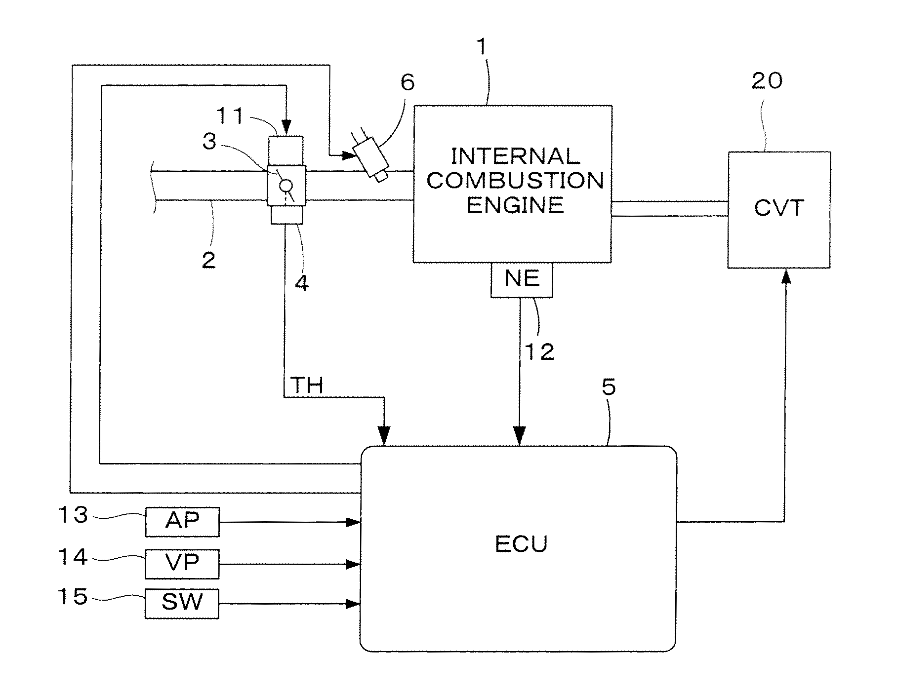
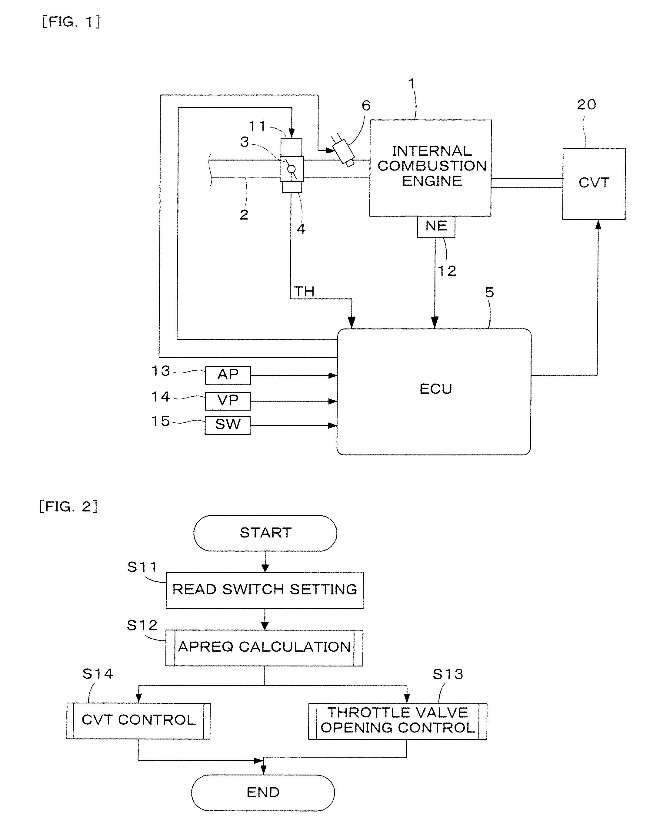
[0026]FIG. 1 is a schematic diagram showing a configuration of an internal combustion engine and a continuously variable transmission which are mounted on a vehicle and a control system therefor according to one embodiment of the present invention. The internal combustion engine 1 (hereinafter referred to as “engine”) has an intake pipe 2 provided with a throttle valve 3. The throttle valve 3 is provided with a throttle valve opening sensor 4 for detecting an opening TH of the throttle valve 3, and a detection signal of the throttle valve opening sensor 4 is supplied to an electronic control unit 5 (hereinafter referred to as “ECU”). An actuator 11 for actuating the throttle valve 3 is connected to the throttle valve 3, and an operation of the actuator 11 is controlled by the ECU 5.

[0027]A fuel injection valve 6 is provided for each cylinder at a position slightly upstream of an...


PUM


Abstract

A demand driving force parameter indicative of a demand driving force of the engine is set based on the accelerator pedal operation amount, and a target value of an engine driving force control amount is set based on the demand driving force parameter. The engine driving force control amount is controlled so as to coincide with the target value. A target rotational speed of the engine is set based on the demand driving force parameter, and the continuously variable transmission is controlled so that the rotational speed of the engine coincides with the target rotational speed. One of a first operation mode and a second operation mode is selectable, wherein the fuel consumption rate in the second operation mode is less than the fuel consumption rate in the first operation mode. When the second operation mode is selected, the demand driving force parameter corresponding to the accelerator pedal operation amount is set to a value which is smaller than a value of the demand driving force parameter in the first operation mode, and the target value is calculated based on a first predetermined characteristic preliminarily set according to the engine rotational speed and the demand driving force parameter. The first predetermined characteristic is set so that the target value corresponding to the same engine rotational speed is substantially constant in a first predetermined range of the demand driving force parameter.

Description

TECHNICAL FIELD[0001]The present invention relates to a control system for a vehicle having a continuously variable transmission and driven by an internal combustion engine, and particularly to a control system for the vehicle whose operation mode is switchable for reducing the fuel consumption rate.BACKGROUND ART[0002]The patent document 1 (listed below) discloses a control system for a vehicle having a continuously variable transmission. According to this system, a target engine rotational speed is calculated for realizing a demand engine output (power) according to an accelerator operation amount at a minimum fuel consumption rate. The gear ratio of the continuously variable transmission is controlled so that an actual engine rotational speed coincides with the target engine rotational speed.[0003]When the gear ratio of the continuously variable transmission is controlled so as to perform the minimum fuel consumption operation as shown in the patent document 1, there is a problem...

Claims


Application Information

Patent Timeline
IPC IPC(8): B60W10/10B60W10/06B60W30/18B60W10/04B60W10/101F02D29/00F16H59/02F16H59/18F16H61/02F16H61/66F16H63/50
CPCB60W10/06B60W10/101B60W30/188B60W50/082B60W2710/0644Y10T477/6242F02D13/0207F02D29/02F16H61/66Y10T477/62427B60W2710/105Y02T10/84B60W2540/10
Inventor EGUCHI, TAKAHIROFUKUDA, TOSHIHIKO
Owner HONDA MOTOR CO LTD
Why Eureka
Try Eureka