System and method for separating gasses in an exhaust gas

Inactive Publication Date: 2011-07-14
PURIFY SOLUTIONS INC
View PDF0 Cites 13 Cited by
  • Summary
  • Abstract
  • Description
  • Claims
  • Application Information

AI Technical Summary

Benefits of technology

In an embodiment of the presently claimed invention, a method is provided for separating carbon dioxide from nitrogen in exhaust gas emitted from a combustion of fuel. In this method, the emitted exhaust gas is compressed in a compressor from ambient pressure to high pressure and then cooled from ambient temperature to liquid carbon dioxide temperature. Liquid carbon dioxide is separated from high-pressure nitrogen gas at liquid carbon dioxide temperature and the separated high-pressure nitrogen gas is used for driving a turbine, which in turn drives the compressor. The method includes exchanging heat between the compressed exhaust gas and nitrogen gas released from the turbine. The exchange of heat may be used to cool the compressed exhaust gas to liquid carbon dioxide temperature and to warm the released nitrogen gas. The turbine may include two or more stages configured to drive the compressor. The method further includes releasing medium pressure nitrogen gas from the first stage of the turbine at cryo-temperature and exchanging heat between the emitted exhaust gas and the medium pressure nitrogen gas to cool the emitted exhaust gas and to heat the medium pressure nitrogen gas. The method also includes driving a second stage of the turbine using the heated medium pressure nitrogen gas and releasing ambient pressure nitrogen gas from the second stage.
In an embodiment of the presently claime

Problems solved by technology

Unfortunately, separation of carbon dioxide from nitrogen requires complex chemist

Method used


Image

  • System and method for separating gasses in an exhaust gas
  • System and method for separating gasses in an exhaust gas
  • System and method for separating gasses in an exhaust gas

Examples


Embodiment Construction

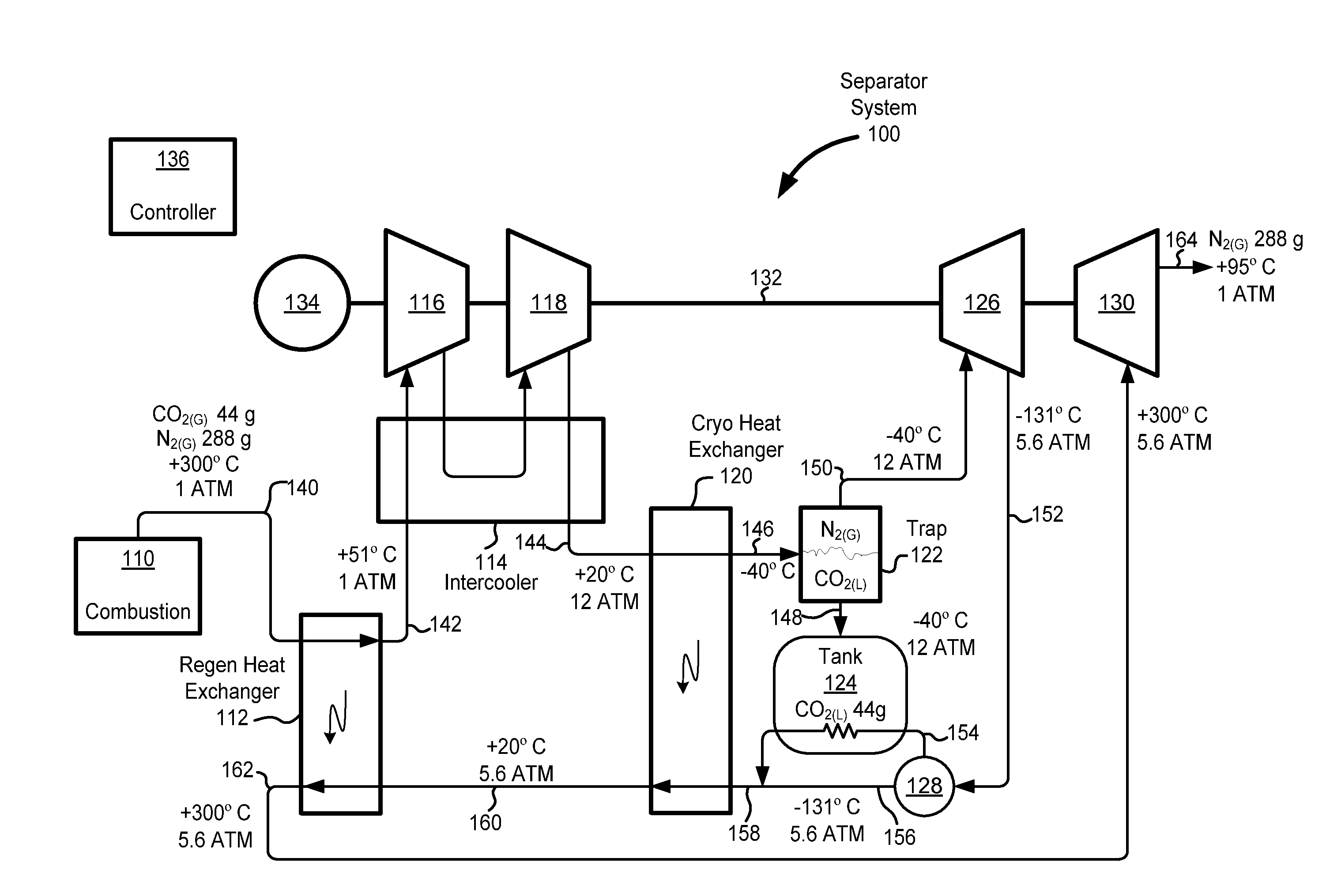
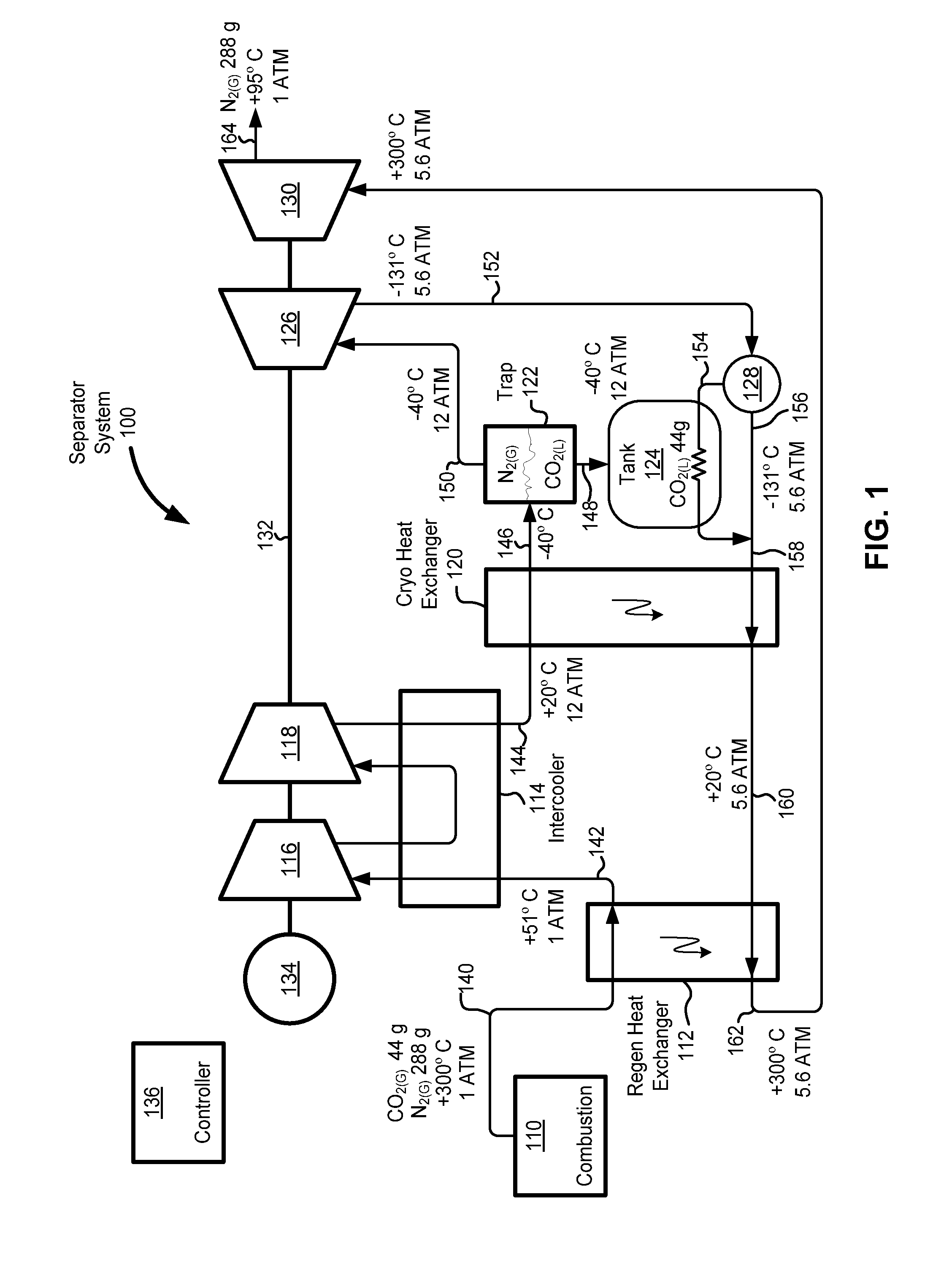
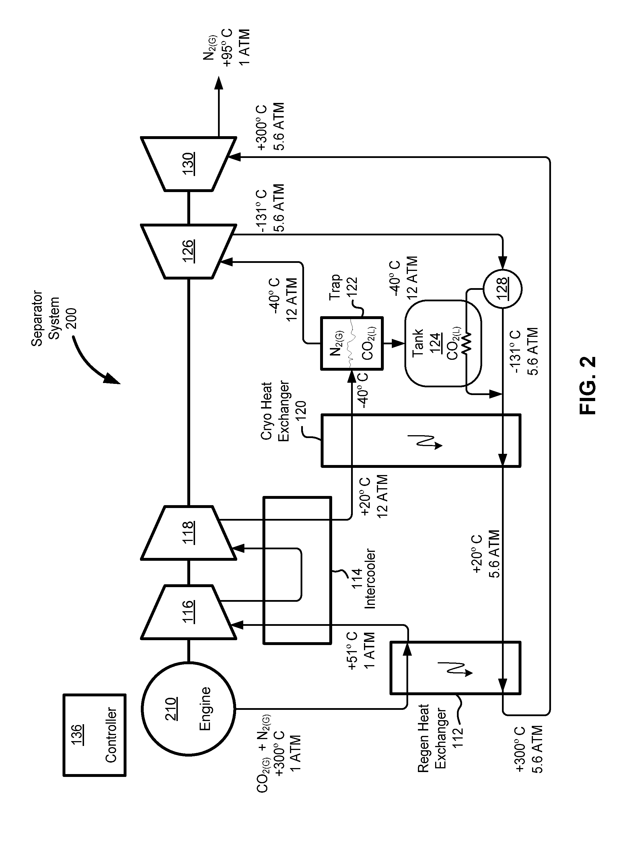
A system is described for compressing and cooling hot exhaust gas to liquid carbon dioxide temperature for separation into liquid carbon dioxide and nitrogen gas, and then heating the nitrogen gas to drive a turbine. The turbine may be coupled to a compressor for compressing the exhaust gas. The turbine may have multiple stages. The system includes one or more heat exchangers between stages of the turbine. The heat exchangers may be used for cooling the exhaust gas while heating nitrogen gas, thus, transferring heat energy from the exhaust gas to the nitrogen gas for use in driving one or more stages of the turbine.

FIG. 1 is a block diagram illustrating an exemplary embodiment of a system 100 for separation of carbon dioxide from nitrogen, according to aspects of the invention. The system 100 includes a regenerative heat exchanger 112, a first stage compressor 116, a second stage compressor 118, an optional intercooler 114, a cryo heat exchanger 120, a fluid trap 122, a tank 124, a ...


PUM


Abstract

A system is provided for separating carbon dioxide emitted in exhaust gas from nitrogen gas. A compressor may be used for compressing the emitted exhaust gas and a heat exchanger may be used for cooling the compressed exhaust gas to liquid carbon dioxide temperatures. The liquid carbon dioxide may be separated from the compressed nitrogen gas and stored. A turbine may use the compressed nitrogen gas to drive the compressor, while further cooling the compressed nitrogen to cryo-temperatures. Heat exchangers may be used for transferring heat energy from emitted exhaust and the compressed exhaust to the cold compressed nitrogen, thus, conserving energy of the system.

Description

BACKGROUND1. Field of the InventionThe present disclosure generally relates to emission control systems. The present disclosure more specifically relates to separating gasses in exhaust emissions from combustion of a fuel.2. Description of Related ArtGenerally ambient air is used for combustion of fuel. Ambient air includes about 80% nitrogen gas and about 20% oxygen. Consequently, exhaust gas emitted from the combustion of fuel primarily includes a mixture of carbon dioxide gas and water vapor produced resulting from the combustion process and nitrogen gas from the ambient air. Water vapor can be condensed from exhaust gas according to standard techniques and safely returned to the environment. Separation of the carbon dioxide from nitrogen is an important step in recovering the carbon dioxide from the emitted exhaust gas. Unfortunately, separation of carbon dioxide from nitrogen requires complex chemistry involving potentially hazardous chemicals and / or substantial amounts of ener...

Claims


Application Information

Patent Timeline
IPC IPC(8): F25J3/00F02C1/04
CPCF25J3/067Y02C10/12F25J2215/04F25J2220/82F25J2230/02F25J2230/04F25J2230/20F25J2230/22F25J2230/30F25J2240/90F25J2270/04F25J2280/02F25J2290/34F25J2290/50F25J2290/62F25J2210/70Y02C20/40
Inventor EVANS-BEAUCHAMP, LINCOLN
Owner PURIFY SOLUTIONS INC
Why Eureka
Try Eureka