

Groove machining tool for use with a thin-film solar cell
a solar cell and groove technology, applied in the direction of manufacturing tools, sustainable manufacturing/processing, final product manufacturing, etc., can solve the problems of inability to say that a groove machined with sufficient quality is available, inability to form a patterning line accurately, and inability to control the angle of the mounting of the tool. , to achieve the effect of simple operation, accurate positioning and controllable mounting angl
- Summary
- Abstract
- Description
- Claims
- Application Information
AI Technical Summary
Benefits of technology
Problems solved by technology
Method used
Image

Examples
first embodiment
Overall Configuration of the Scribe Device
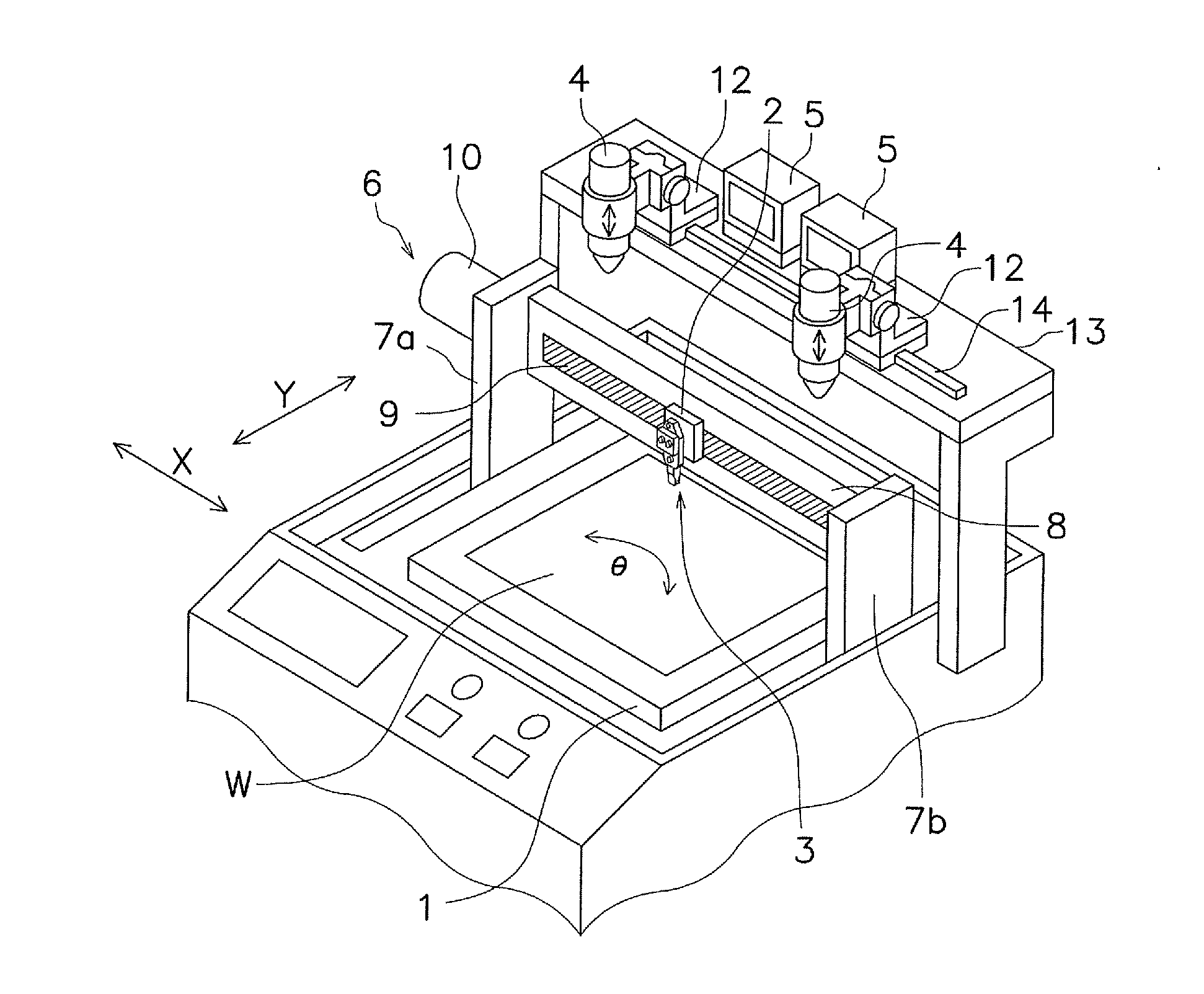
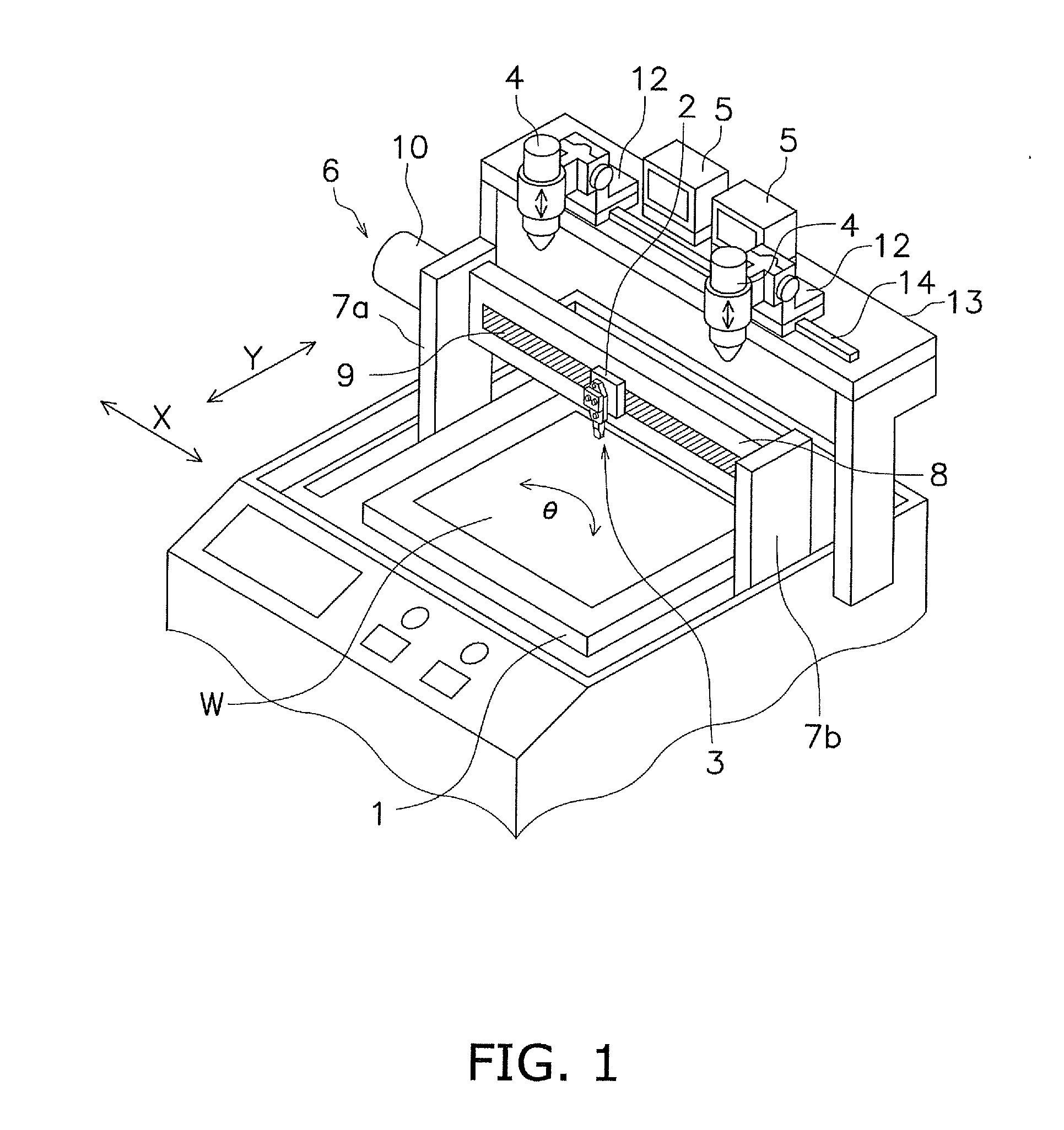
[0046]This device includes a table 1, onto which a solar cell substrate W is placed, a scribe head 2, a holder assembly 3 installed onto the scribe head 2, and two cameras 4 and two monitors 5.
[0047]The table 1 can move in the horizontal plane, in a Y direction in FIG. 1. Also, the table 1 is freely rotatable within the horizontal plane.
[0048]The scribe head 2 can move in an X and the Y directions on top of the table 1 via a movement control mechanism 6. As illustrated in FIG. 1, the X direction is orthogonal to the Y direction in the horizontal plane. The movement control mechanism 6 includes one pair of support pillars 7a and 7b, a guide bar 8 crossing between the pair of support pillars 7a and 7b, and a motor 10 that moves a guide 9 formed on the guide bar 8. The scribe head 2 can move, as previously stated in the X direction along the guide 9. An air cylinder (not shown) is disposed on the scribe head 2 and the air cylinder allows the ho...
experimental example
[0070]FIGS. 5A to 5C show a monitor image of a case wherein the groove machining tool according to the present embodiment is used to remove the thin film. FIG. 5A shows a case wherein a tool having a blade 25 with a tilt angle of α=0° is used to machine at movement speeds of 100 mm / sec, 400 mm / sec, and 800 mm / sec. FIG. 5B shows a case wherein a tool having a blade 25 with a tilt angle of α=20° is used to machine at the same movement speeds. FIG. 5C shows a case wherein a tool having a blade 25 with a tilt angle of α=30° is used to machine at the same movement speeds. In each drawing, the portions shown in white are portions that have been groove machined, and the portions shown in black are portions where the thin film remains. The upper end of the groove shown in the drawings is the portion that contacts the second face 24e of the blade tip part 24.
[0071]As is clear from the drawings, the thin film is removed in a wave shape at both ends of the groove when α=0°, and the machining q...
second embodiment
[0083]According to the first embodiment, the blade 25 of the blade tip part 24 was placed at only one end in the direction of movement of the tool. However, it is acceptable to place blade tip parts 34 and 34′ at both ends in the direction of movement of the tool, as illustrated in FIGS. 7A and 7B. FIGS. 7A and 7B are drawings of the blade tip part 34 as viewed from a bottom face.
[0084]Specifically, the blade tip part 34 illustrated in FIG. 7A has a bottom face 34a, an anterior face 34b and a posterior face 34c, and a first face 34d and a second face 34e, which are opposing faces. Blades 35a and 35b exist at the bottom end of each of the anterior face 34b and the posterior face 34c of the blade tip part 34 and extend in a direction intersecting the direction of movement M of the tool. The blades 35a and 35b of the blade tip part 34 are tilted at the same angle and in the same direction as each other with regard to a direction orthogonal to the direction of movement M of the tool.
[00...
PUM
| Property | Measurement | Unit |
|---|---|---|
| Thickness | aaaaa | aaaaa |
| Angle | aaaaa | aaaaa |
Abstract
Description
Claims
Application Information