RF coil docking station for magnetic resonance systems

Inactive Publication Date: 2011-07-14
KONINKLIJKE PHILIPS ELECTRONICS NV
View PDF9 Cites 27 Cited by
  • Summary
  • Abstract
  • Description
  • Claims
  • Application Information

AI Technical Summary

Benefits of technology

[0011]One advantage resides in more efficient, precise, and accurate coil selection.
[0012]Another advantage resi

Problems solved by technology

One consequence of these developments is that the selection and maintenance of RF coils is becoming increasingly complex.
As the number of available coils in a typical MR scanner facility increases, it becomes increasingly difficult to identify the best coil, coil pre-formed coil assembly, or set of individual coils, for a particular imaging session or task.
However, bore space limitations and the need for compatibility with high magnetic fields used in MR tend to limit the amount of on-board diagnostics that manufacturers are willing to incorporate into

Method used


Image

  • RF coil docking station for magnetic resonance systems
  • RF coil docking station for magnetic resonance systems
  • RF coil docking station for magnetic resonance systems

Examples


Example

[0018]Corresponding reference numerals when used in the various figures represent corresponding elements in the figures.

DETAILED DESCRIPTION OF EMBODIMENTS

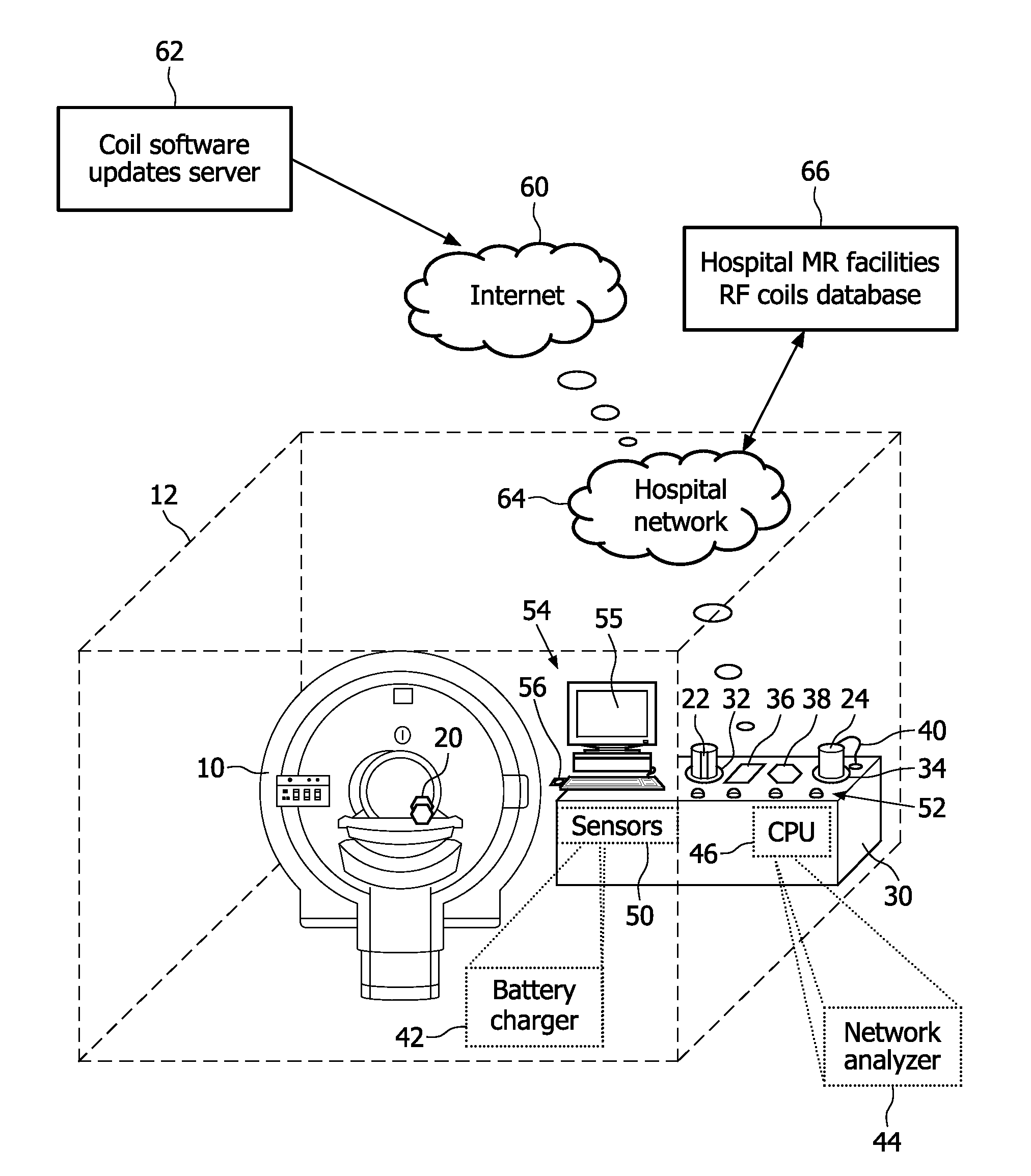
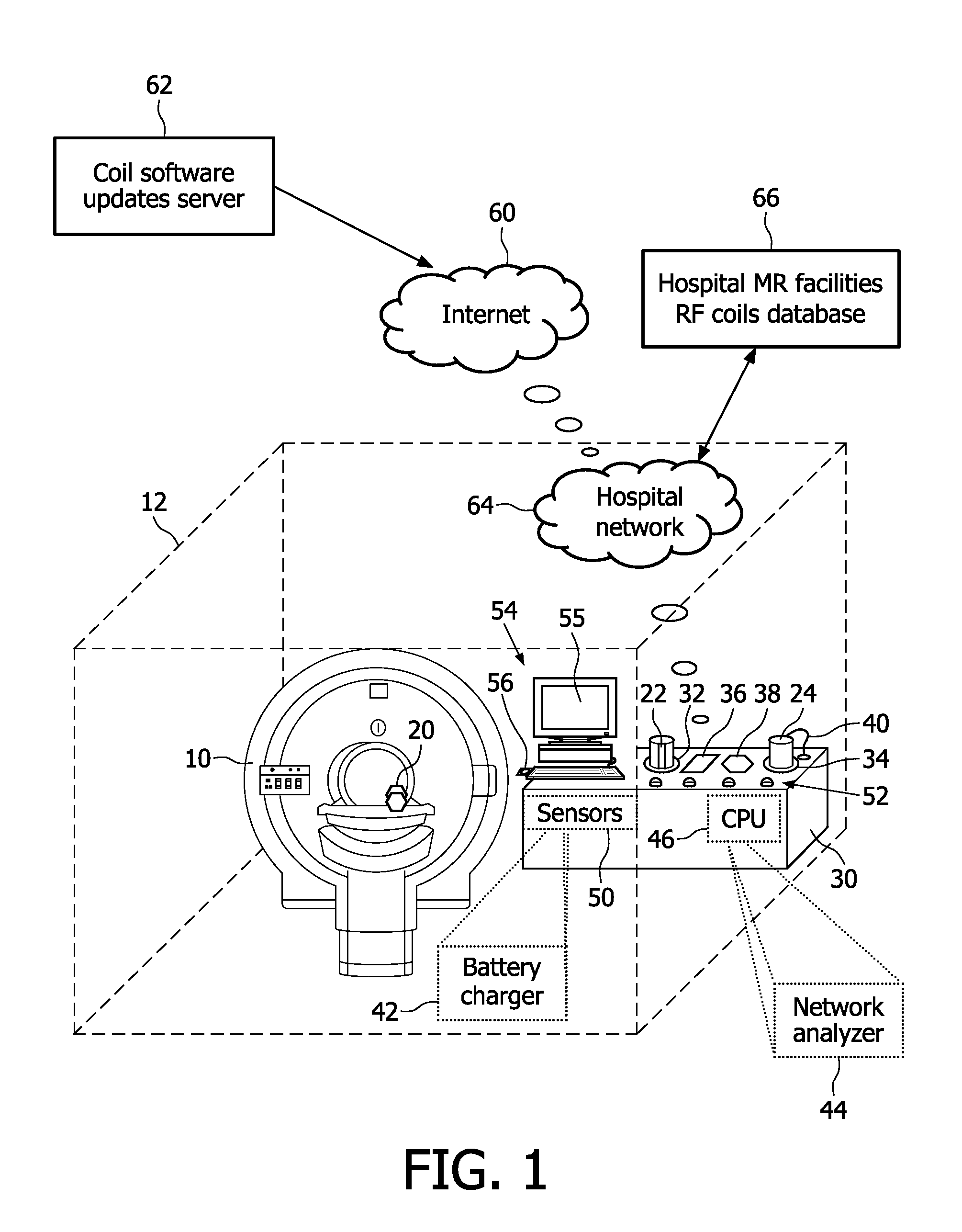
[0019]With reference to FIG. 1, a magnetic resonance system includes a magnetic resonance scanner 10 disposed in a shielded room 12 that provides at least some radio frequency isolation between the magnetic resonance scanner 10 and the environment outside of the shielded room 12. The magnetic resonance scanner 10 can be substantially any type of magnetic resonance scanner, including the illustrated closed horizontal bore-type scanner, an open-bore scanner, a vertical magnetic resonance scanner, or so forth. As some illustrative examples, some suitable embodiments of the magnetic resonance scanner 10 include the Achieva™ or Intera™ closed horizontal-bore scanners or the Panorama™ open-bore scanners, each of which is available from Koninklijke Philips Electronics N.V. (Eindhoven, the Netherlands). The magnetic resonance scanner 10 i...


PUM


Abstract

An RF coil docking station (30) comprises: an RF coil receptacle (32, 34, 36, 38) configured to receive and store an RF coil (20, 22, 24) and to convey data between the RF coil docking station and the stored RF coil (22, 24); and a processor (46, 54) configured to control conveyance of data between the RF coil docking station and the stored RF coil to modify an operational state of the stored RF coil. In some embodiments, the RF coil docking station (30) comprises a plurality of RF coil receptacles (32, 34, 36, 38) configured to receive and store RF coils and to identify the stored RF coils, the processor is configured to select one or more of the stored RF coils for performing an identified magnetic resonance procedure (90), and an indicator (52, 55) is configured to indicate the selected one or more of the stored RF coils.

Description

FIELD OF THE INVENTION[0001]The following relates to the magnetic resonance and related arts.BACKGROUND OF THE INVENTION[0002]Magnetic resonance (MR) scanners and systems are employing increasingly sophisticated coils and coil array assemblies. Coils are designed for highly specific applications, such as brain imaging, joint (e.g., knee or elbow) imaging, various types of chest or torso imaging, and so forth. Pre-formed coil array assemblies are designed to be optimized for SENSE imaging or other parallel imaging techniques applied to specific anatomical regions. On the other hand, some parallel imaging applications may be better performed using a plurality of suitably placed individual receive coil loops. Some coils include transmit capability, while others are receive-only coils and rely upon a whole-body transmit coil integral with the MR scanner, or upon another transmit coil, in order to perform a complete magnetic resonance sequence. Different coils may have different capacita...

Claims


Application Information

Patent Timeline
IPC IPC(8): G01R33/44G06F9/445G01K1/00
CPCG01R33/288G01R33/3415G01R33/3692G01R33/3657G01R33/3635
Inventor LEUSSLER, CHRISTOPH
Owner KONINKLIJKE PHILIPS ELECTRONICS NV
Why Eureka
Try Eureka