
Precalibrated dental implant aid

a technology of dental implants and aids, applied in dentistry, dental prosthetics, medical science, etc., can solve the problems of insufficient accuracy of most current intra-oral scanners, difficult to measure with the required accuracy, and many versions of rather complex geometric designs of implant heads, etc., to reduce the time for completion, speed and simple technique, the effect of simplifying the process

Inactive Publication Date: 2016-01-21
GC EURO
View PDF1 Cites 14 Cited by
  • Summary
  • Abstract
  • Description
  • Claims
  • Application Information

AI Technical Summary

Benefits of technology

The present invention provides a fast and simple technique to collect both identity and spatial information about a dental implant and its underlying dental structures. This technique allows for a dental restoration to be prepared faster and easier, as it only requires information about a few markers. It is also more efficient and cost-effective compared to alternatives that involve a partial destruction of healthy dental structures. The visualiser is produced more easily and quickly using a variety of manufacturing methods. It is easy to connect to the dental implant and can be visualised using simple spatial visualisation techniques, such as current intra-oral cameras or 2D visualisation techniques. In summary, the invention simplifies the process and reduces the time for dental restorations, allowing for more patients to select this implant-based process and preserving more of the existing healthy dental structures.

Problems solved by technology

This results in various versions of rather complex geometric designs of the implant head, which are difficult to measure with the required accuracy, even by means of the newly evolving intraoral measuring methods.
A major issue in the drilling of the hole for the implant is the care to avoid all the vital structures, in particular the inferior alveolar nerve (IAN) canal and the mental foramen within the mandible (=lower jaw bone), but also the maxillary sinus cavity in the upper jaw.
If the implant becomes loaded too soon, it is possible that the implant may move, which results in failure.
The typical long time, until the final restoration may eventually be brought in place, is however often a serious deterrent for patients considering implants as a possible alternative to other solutions, in particular when it concerns the so-called “aesthetic” region.
The accuracy of most current intra-oral scanners is not yet sufficiently high.
In case of a very difficult spatial situation in the mouth, the current bulky intra-oral scanners may also not sufficiently reach the region to be captured.
Finally but not in the least, it is for most patients a very uncomfortable situation if several scans have to be taken.
The disadvantage of this disclosure is that the markers are only information carriers and may bring only dimensional information about one particular object or th assembly of implant with the abutment.
The drawback of this method is that human intervention is required, which introduces a possibility for errors.
A further problem with this method is that it again requires a 3D scan of the adaptor, that a high number of scanning points is required, and that the method is thus rather time consuming.
A further problem is that the number of suitable variations of scan bodies remains limited.
Such a scan adaptor with geometric distortions has the drawback that the method requires elaborate calibration of the measuring equipment.
A further disadvantage is that the scan adaptor needs to be made with high precision.
Also in this method, the exact type of the implant and its connection details need to be entered into the data file by an operator, whereby the possibility for errors remains.
A major disadvantage of all of the above described dental scan adaptors is that their use requires at least one 3D-scan, usually several, of the patients oral cavity, possibly in more than one scan of different portions of the mouth, or of a plaster model made from a mould taken from the patients oral cavity.
Such a 3D scan is still rather time consuming.
Not only the scan itself may introduce further errors due to limited accuracy of the scanners but also the manufacturing method of the adapter has a limited accuracy which may only be increased with high precision methods, which are elaborate and costly.
Such accuracies are below the capabilities of most 3D scanners currently available in the industry.
Another disadvantage is that in many instances the identity of the underlying implant, as well as its connection details, still has to be obtained from another source, usually by human input, which adds the problem that this procedure remains prone to human error.
A significant problem with the 3D-scan is that the scanning itself is a time consuming procedure.
When the mouth of a patient is scanned, the procedure requires the full immobilization of the patient's head or lower jaw relative to the scanning apparatus, during such a long period that it becomes significantly inconvenient to the patient.
Another problem is that a plaster model is more readily accessible to the scanner from all sides, while the access for scanning a patient's mouth is much more restricted.
The number of possible combinations remained however rather limited.
The problem with the dental scan adaptor techniques as known in the art is that they require an elaborate 3D-scan, which is a time consuming procedure.
As stated above, the scanning of a part of the patient's mouth brings such inconveniences that these usually drive the patient and / or the dentist towards the intermediate step of building a plaster model, an additional step which adds significantly more time to the total period that the patient is waiting for the full dental restoration, which usually is particularly disturbing when the restoration is in the so-called “aesthetic” region.
The drawback of the method of U.S. Pat. No. 5,401,170 is that on the one hand the method with the laser beam scanning is time consuming and thus inconvenient to the patient.
In addition, no information is collected in either methods about the exact type of the implant and its connection details.
This information also has to be entered into the data file by an operator, whereby there is always a possibility for making errors.
The exact type of the implant and its connection details are not available from the measuring device or its picture, and need to be entered into the data file by an operator, whereby the possibility for errors remains

Method used


Image

  • Precalibrated dental implant aid
  • Precalibrated dental implant aid
  • Precalibrated dental implant aid

Examples


examples

The Pre-Calibration Step:

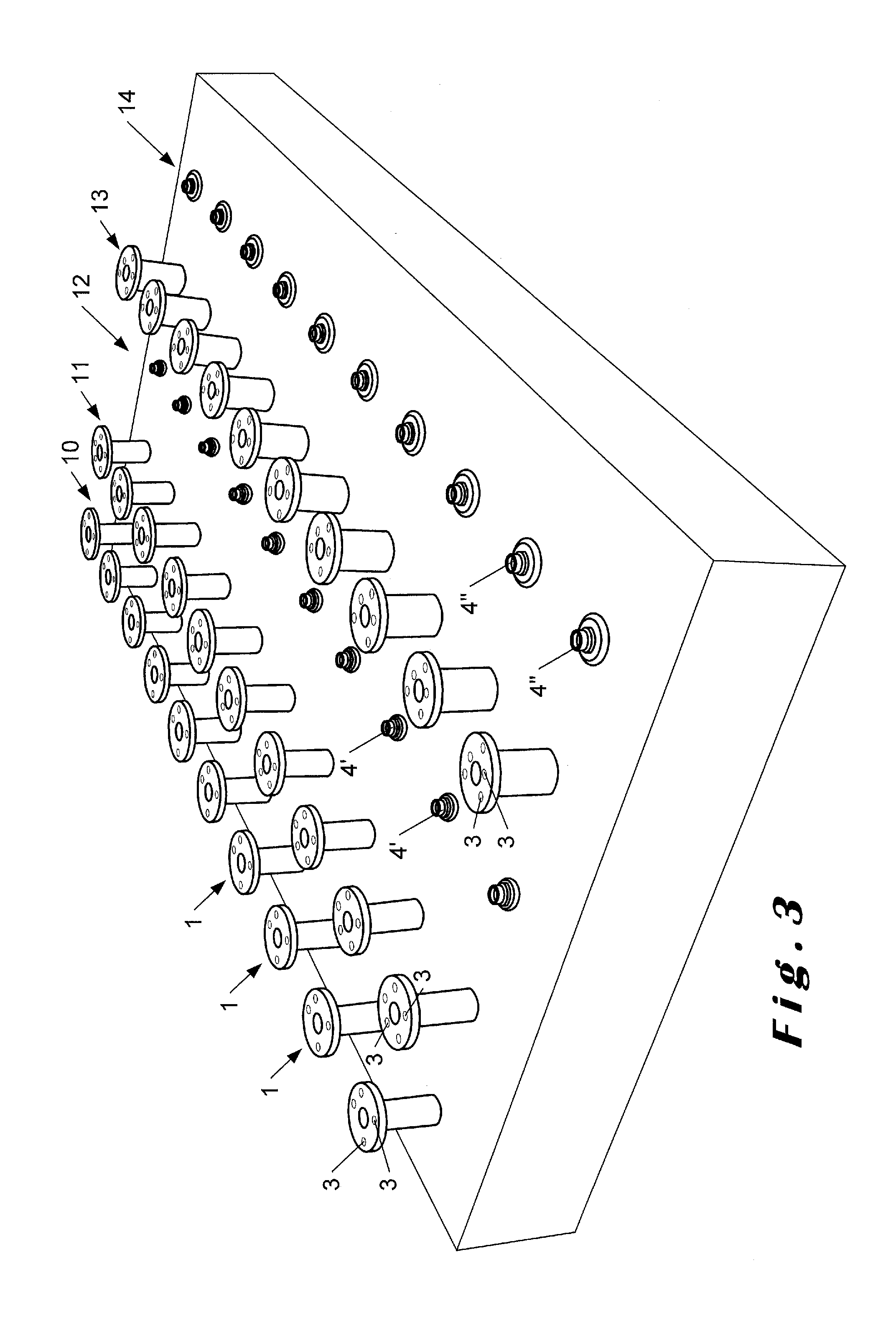
[0139]In a plate a matrix of 5×10 dental implant root connection part analogues are placed, as shown in FIG. 3. The connection parts may all be the same, but preferably differ in order to reflect a portion of the wide variety of connections for implant roots, their analogues, and for their corresponding abutments. For each position, the type of connection, as well as the axis of orientation of the implant root, are well defined relative to the plate.

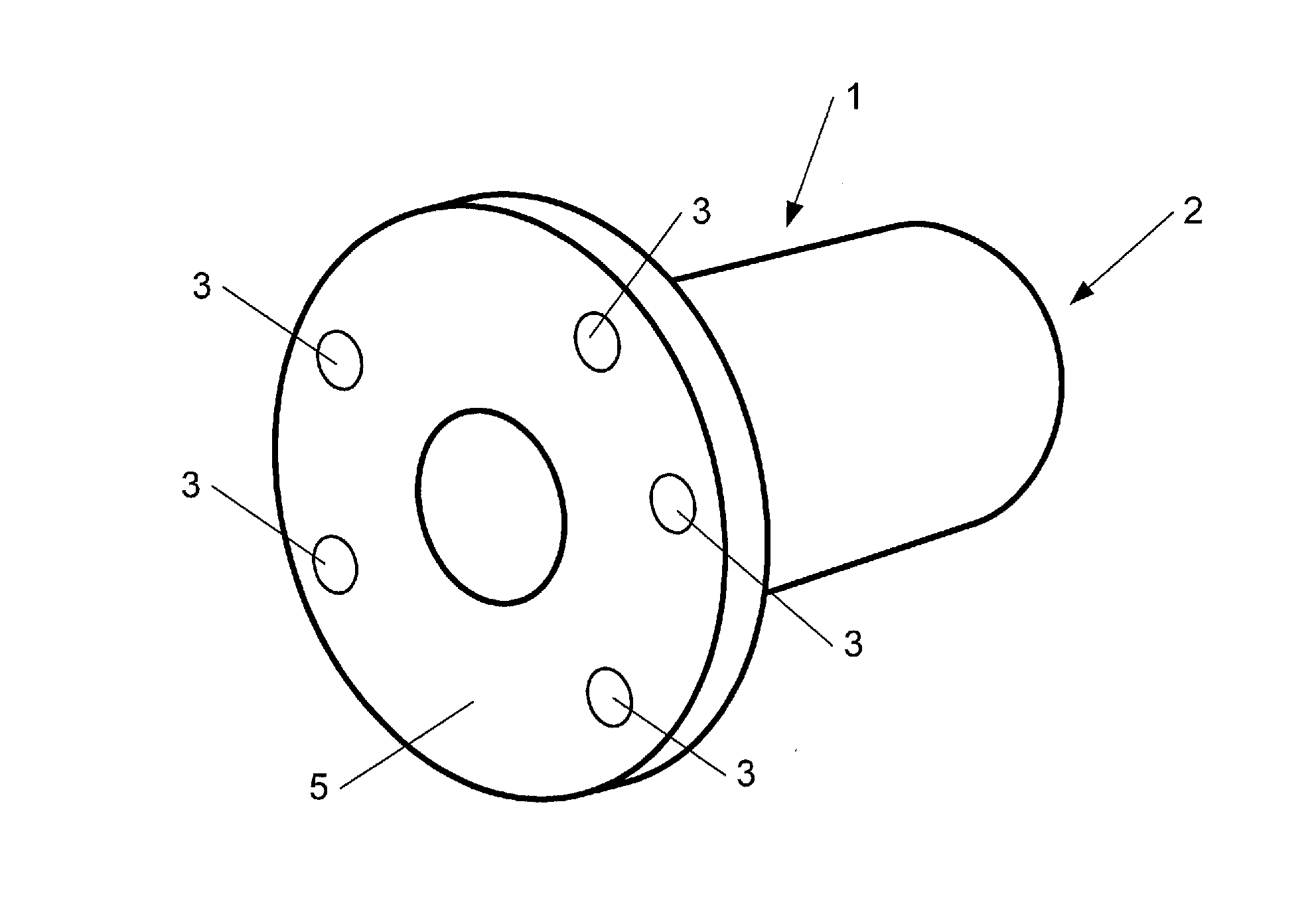
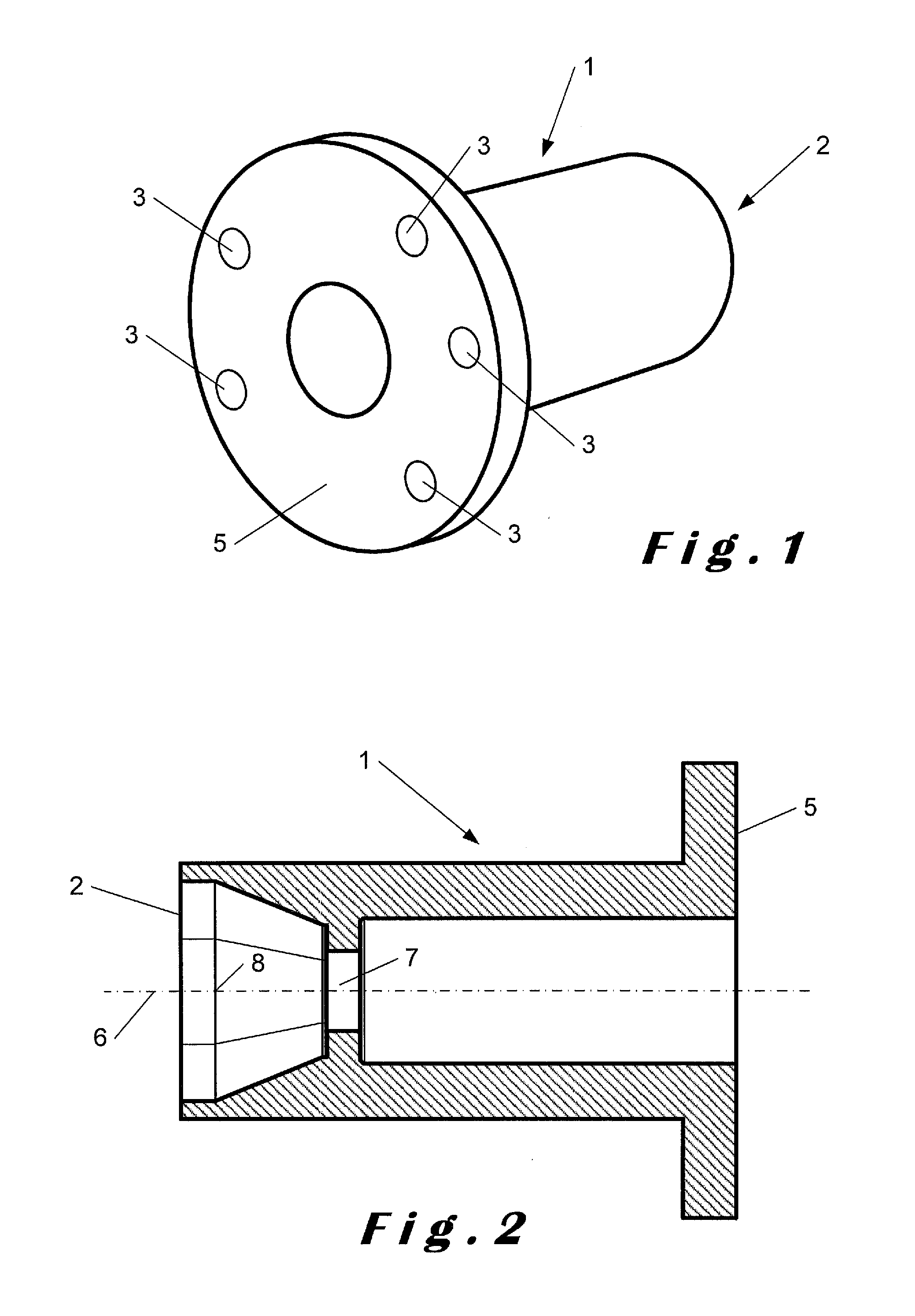
[0140]To each one of the implant root connection parts is properly connected a corresponding visualiser, as shown in FIG. 3 for three rows. All the visualisers in this example have a cylindrical shape with a flat head which extends cylindrically beyond the size of the cylindrical shape of the visualiser. Such a visualiser is shown in more detail in FIGS. 1 and 2. On the flat head of each visualiser are subsequently placed the markers. The markers may form the same pattern for implant connection parts which are th...


PUM


Abstract

Disclosed is a kit in parts comprising(i) a visualiser for a dental implant which comprisesa) a mechanical connection part to a predetermined implant root defining, relative to the visualiser, the vector of the implant root along the axis of orientation, andb) at least three markers, contrasting under electromagnetic radiation with their an observable and recognizable by an electromagnetic recognition technique, whereby the markers define a geometric pattern of which the recognition technique is capable of collecting the spatial information, and(ii) a data file from which the spatial information of the geometric pattern may be retrieved and referenced to information determining the vector of the implant root relative to the pattern, and also identifying the visualiser and the predetermined implant root.Further disclosed is a method for preparing a dental prosthesis using the kit, as well as the visualiser itself.

Description

FIELD OF THE INVENTION[0001]The present invention relates generally to the field of dental implant systems. More particularly, the invention relates to dental implant visualizers or beacons, intended for providing a function similar to what is currently provided by a dental implant scan adapter or dental scan adaptor.BACKGROUND OF THE INVENTION[0002]What is currently known as a dental scan adaptor, scan body or scan locator is an essential tool in the preparation and fabrication of a dental prosthesis for a patient who has one or more dental implants fixed into his or her jawbone.[0003]A dental implant is a “root” device, used in dentistry to support restorations that resemble a tooth or group of teeth to replace missing teeth. Dental implants may be used to support a number of dental prostheses, including crowns, implant-supported bridges or dentures. They may also be used as anchorage for orthodontic tooth movement.[0004]A typical dental implant consists of a small titanium screw ...

Claims


Application Information

Patent Timeline
Patent Type & Authority Applications(United States)
IPC IPC(8): A61C1/08A61C8/00A61C9/00
CPCA61C8/0089A61C9/004A61C1/084A61C8/0001A61C8/005A61C8/006A61C8/0068A61C9/0053
Inventor MILTAU, KEVINBOGAERTS, WALTERWEISS, OEZLEM
Owner GC EURO
Learn More