
Combiner for doherty amplifier

a technology of doherty amplifier and directional coupler, which is applied in the direction of amplifiers, amplifiers with semiconductor devices/discharge tubes, electrical apparatus, etc., can solve the problems of large power consumption loss, and large loss of directional coupler

Inactive Publication Date: 2011-07-14
NGK INSULATORS LTD
View PDF14 Cites 40 Cited by
  • Summary
  • Abstract
  • Description
  • Claims
  • Application Information

AI Technical Summary

Benefits of technology

The present invention provides a Doherty amplifier combiner that can improve problematic gain and phase distortions of a Doherty amplifier without reducing the efficiency of the amplifier. The combiner is made up of a reduced number of parts, making it small and light. The combiner includes a first input terminal for receiving the output signal from the carrier amplifier, a second input terminal for receiving the output signal from the peak amplifier, an output terminal for outputting the combined output signal, a first λ / 4 line connected between the first input terminal and the combining point, a second λ / 4 line connected between the second input terminal and the combining point, signal monitoring means for monitoring the signals flowing through the first and second λ / 4 lines, and an inner-layer shield electrode disposed between the first and second λ / 4 lines. The combiner can be made using a dielectric substrate with a plurality of stacked dielectric layers. The technical effect of the invention is to improve the performance of Doherty amplifiers without adding complexity or reducing efficiency.

Problems solved by technology

The signal which passes through the directional coupler is output from the Doherty amplifier and hence has a high power level ranging from several tens W to several hundreds W. However, the directional coupler loses a large amount of electric power because it causes a large power consumption loss.
Due to errors caused when a circuit board on which the Doherty amplifier combiner and the directional coupler are mounted is manufactured and errors when the Doherty amplifier combiner and the directional coupler are installed on the circuit board, the output signal from the directional coupler tends to change in level and phase, and hence the digital processor tends to fail to carry out a sufficient corrective process.

Method used


Image

  • Combiner for doherty amplifier
  • Combiner for doherty amplifier
  • Combiner for doherty amplifier

Examples


1st example

The output characteristics of Comparative example 1 and Inventive examples 1 through 3 were confirmed.

##ventive example 1

Inventive Example 1

An ordinary Doherty amplifier 16 and the ninth combiner 10I shown in FIGS. 23 and 24 were mounted on a circuit board, a carrier amplifier 12 was connected to the carrier input terminal 26 of the ninth combiner 10I, and a peak amplifier 14 was connected to the peak input terminal 28 of the ninth combiner 10I.

The gain and amplifier efficiency of the Doherty amplifier 16 were measured based on a signal output from the third monitor circuit 50c connected to the third monitor terminal 36c. The output signal from the ninth combiner 10I was of 52.9 dBm.

The ninth combiner 10I, which includes the combining section and the third directional coupler 40C integrally formed with each other in the dielectric substrate 42, caused a power loss of 3.9 W, which showed an improvement of 4.4 W over Comparative example 1. As the amplifier efficiency of the Doherty amplifier was of 45%, the electric power consumption was improved by 9.8 W. The improvement was considered to result from t...

##ventive example 2

Inventive Example 2)

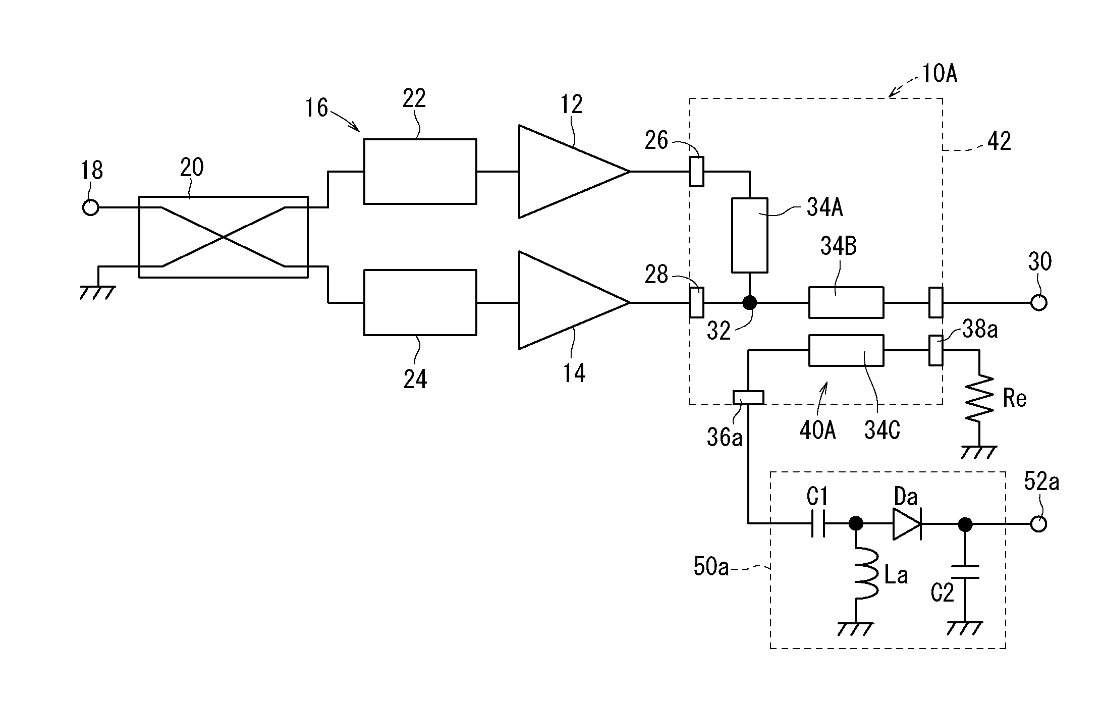
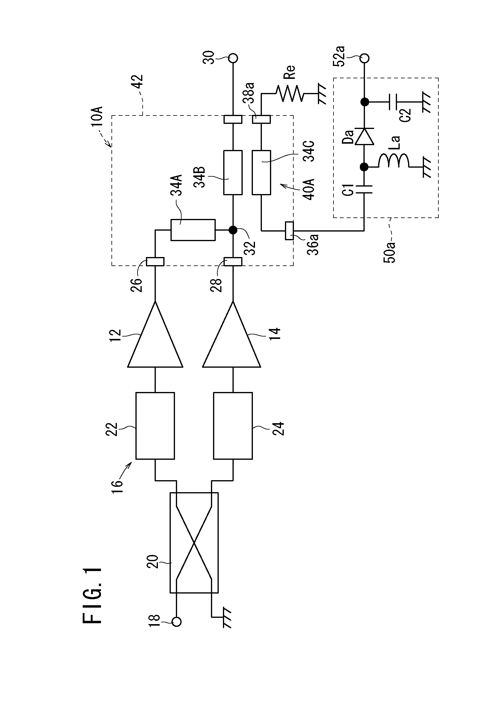
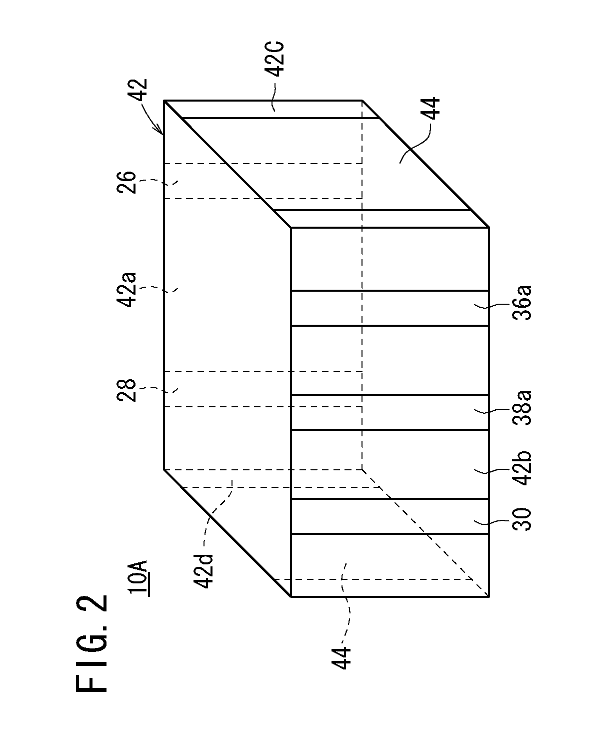
An ordinary Doherty amplifier 16 and the first combiner 10A shown in FIGS. 1 through 3 were mounted on a circuit board, a carrier amplifier 12 was connected to the carrier input terminal 26 of the first combiner 10A, and a peak amplifier 14 was connected to the peak input terminal 28 of the first combiner 10A.

The gain and amplifier efficiency of the Doherty amplifier 16 were measured based on a signal output from the first monitor circuit 50a connected to the first monitor terminal 36a. The output signal from the first combiner 10A was of 52.95 dB, which showed an improvement of 6.7 W over Comparative example 1. The electric power consumption was improved by 14 W.

The improvement was considered to result from the fact that Inventive example 2 was free of the wiring loss caused by the mounted microstrip line 202 in Comparative example 1 and the loss caused by the added directional coupler 204.


PUM


Abstract

A combiner for a Doherty amplifier includes, on and in a dielectric substrate, a carrier input terminal, a peak input terminal, an output terminal, a combining point for combining an output signal from the carrier amplifier and an output signal from the peak amplifier, a first λ / 4 line connected between the carrier input terminal and the combining point, a second λ / 4 line connected between the combining point and the output terminal, and a first directional coupler. The first directional coupler includes a third λ / 4 line electromagnetically coupled to one, to be monitored, of the first λ / 4 line and the second λ / 4 line.

Description

BACKGROUND OF THE INVENTION1. Field of the InventionThe present invention relates to a combiner for being connected to the output stage of a Doherty amplifier and combining an output signal from a carrier amplifier and an output signal from a peak amplifier.2. Description of the Related ArtRecently, cellular telephone base stations have incorporated transmission amplifiers for communicating with cellular telephones that are present in the areas covered by the base stations. The transmission amplifier is required to be adapted for an increased number of cellular telephones in the areas and an increased communication rate which results from and wider usage of data communications in the cellular telephone environment. Therefore, the transmission amplifier needs to reduce a gain distortion and a phase distortion of its output signal. The transmission amplifier is a circuit with maximum electric power consumption in the base station. Consequently, it is important for cellular telephone s...

Claims


Application Information

Patent Timeline
Patent Type & Authority Applications(United States)
IPC IPC(8): H01P5/12
CPCH01P5/12H01P5/187H03F2200/204H03F3/602H03F1/0288
Inventor NAMERIKAWA, MASAHIKOYANO, SHINSUKEHORIO, YASUFUMITSURUOKA, TATSUYAHIRAI, TAKAMIOKUBO, HIDEAKIMIZUMA, ATSUO
Owner NGK INSULATORS LTD
Learn More