Method for UV photolytic separation of pollutant gases from an emission stream

a technology of pollutant gas and photolysis separation, which is applied in the direction of separation process, liquid degasification, dispersed particle separation, etc., can solve the problems of reducing the overall thermal efficiency of the power plant from 39% to 29%, and energy-intensive cosub>2 /sub>from the amine solution

Inactive Publication Date: 2011-07-14
OMOTOWA BAMIDELE A
View PDF8 Cites 1 Cited by
  • Summary
  • Abstract
  • Description
  • Claims
  • Application Information

AI Technical Summary

Benefits of technology

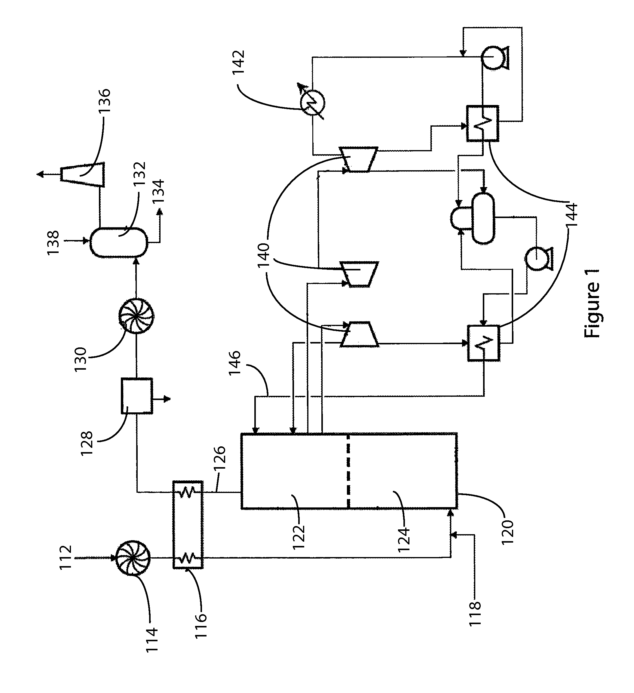
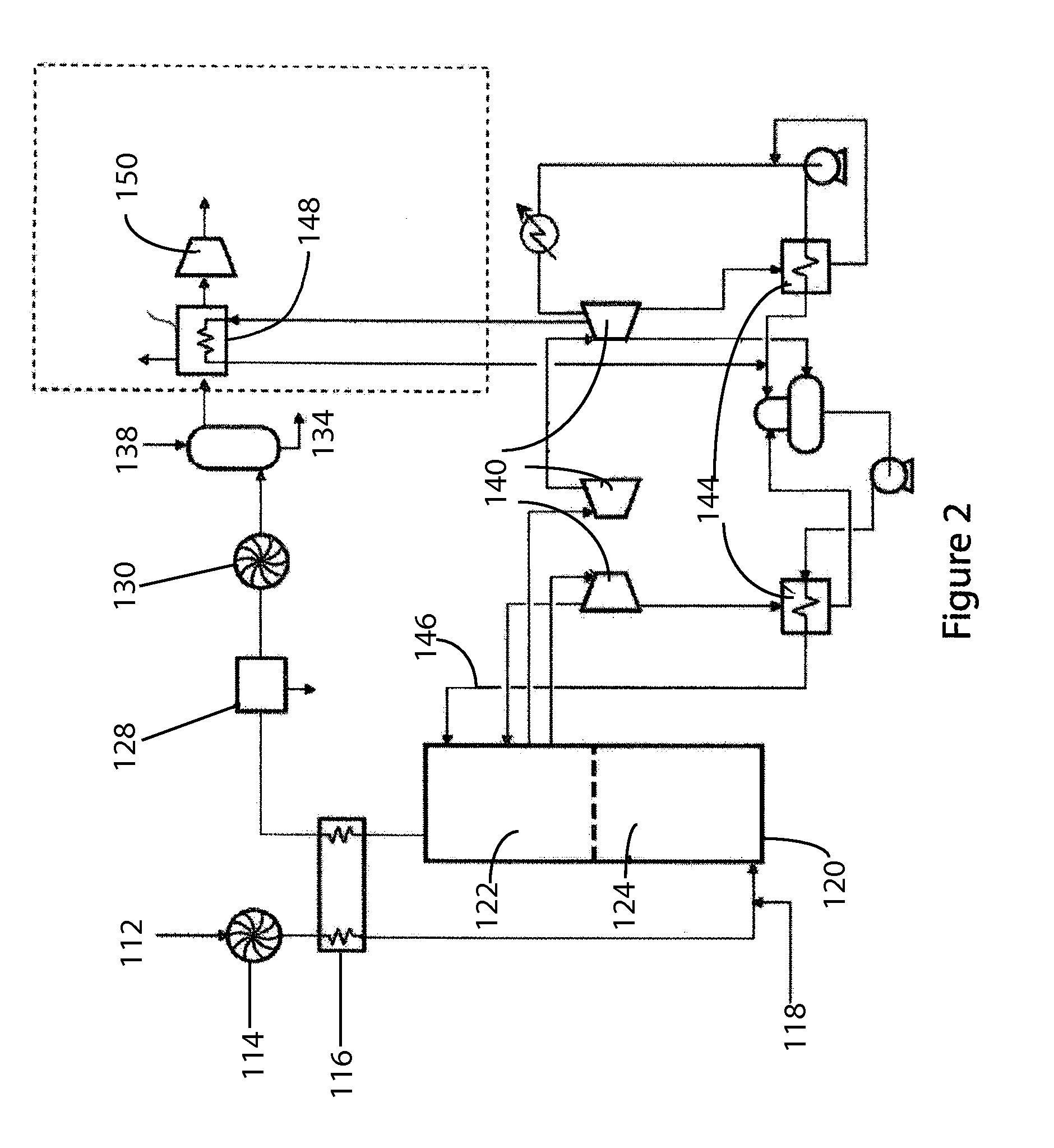
[0010]The photolytic process has the potential to dramatically cut the 30% increase in coal usage by more than half, a dramatic reduction that will significantly reduce the cost of capturing CO2 and improve the acceptance of carbon capture by companies that operate coal-fired plants. The disclosed technology has capacity to capture more than 90% of the six to ten thousand tons per day of CO2 produced by a 500 MWe coal-fired power plant, as an example.
[0011]One aspect of the disclosed technology transforms the current state-of-the-art MEA technology by replacing the current energy parasitic thermal processes with a photochemical process. Photolysis is an innovative and novel alternative source of energy using UV photons. Studies have shown that photolysis, providing energy in the form of photons, can effectively replace the thermal process with a significant reduction in required energy and with efficiency comparable to the current thermal MEA technology for CO2 desorption in a continuous process. The disclosed technology reduces the parasitic COE to less than 50% of the current burden. Research has shown that photochemical reactions are several orders of magnitude faster and use significantly less energy than conductive thermal processes. As a result, some industries, like the manufacture of photoresist in microelectronic components, are using ultraviolet light emitting diodes (UV LEDs) to power energy efficient and effective photochemical processes.
[0012]The disclosed photochemical technology has two additional significant benefits. First, it builds on the state-of-the-art MEA technology. Second, since it replaces only the thermal process in MEA technology, it has the potential to be cost effectively retrofitted into existing plants with minimal down time.
[0016]By using available efficiencies of electricity powered UV generation, the disclosed photochemical technology has the potential to cut the parasitic power demands of the current thermal technology by almost half; from 16% to only 9.1%. This will reduce the cost of removing a ton of CO2 from the current efficiency at $51 / t to only about $35 / t of CO2 separated.

Problems solved by technology

CO2 capture requires more coal because it creates a 24% parasitic energy demand by CO2 absorption, desorption, and compression unit operations.
Because of this huge added cost, coal-fired plants are resistant to adding CO2 capture technology.
Unfortunately, coal will continue to be used as a major source of power generation in the U.S. for the foreseeable future, and according to the World Coal Institute, coal's share in global electricity generation is set to increase from 41% to 44% by 2030.
Unfortunately, even using the MEA technology dramatically drops a power plant's overall thermal efficiency from 39% to 29%.
However, thermally extracting the CO2 from the amine solution is energy intensive and incurs burning 30% more coal than is necessary to generate electricity.
The thermal process increases the cost of electricity (COE) by 81% for a supercritical pulverized coal plant.

Method used


Image

  • Method for UV photolytic separation of pollutant gases from an emission stream
  • Method for UV photolytic separation of pollutant gases from an emission stream
  • Method for UV photolytic separation of pollutant gases from an emission stream

Examples


Embodiment Construction

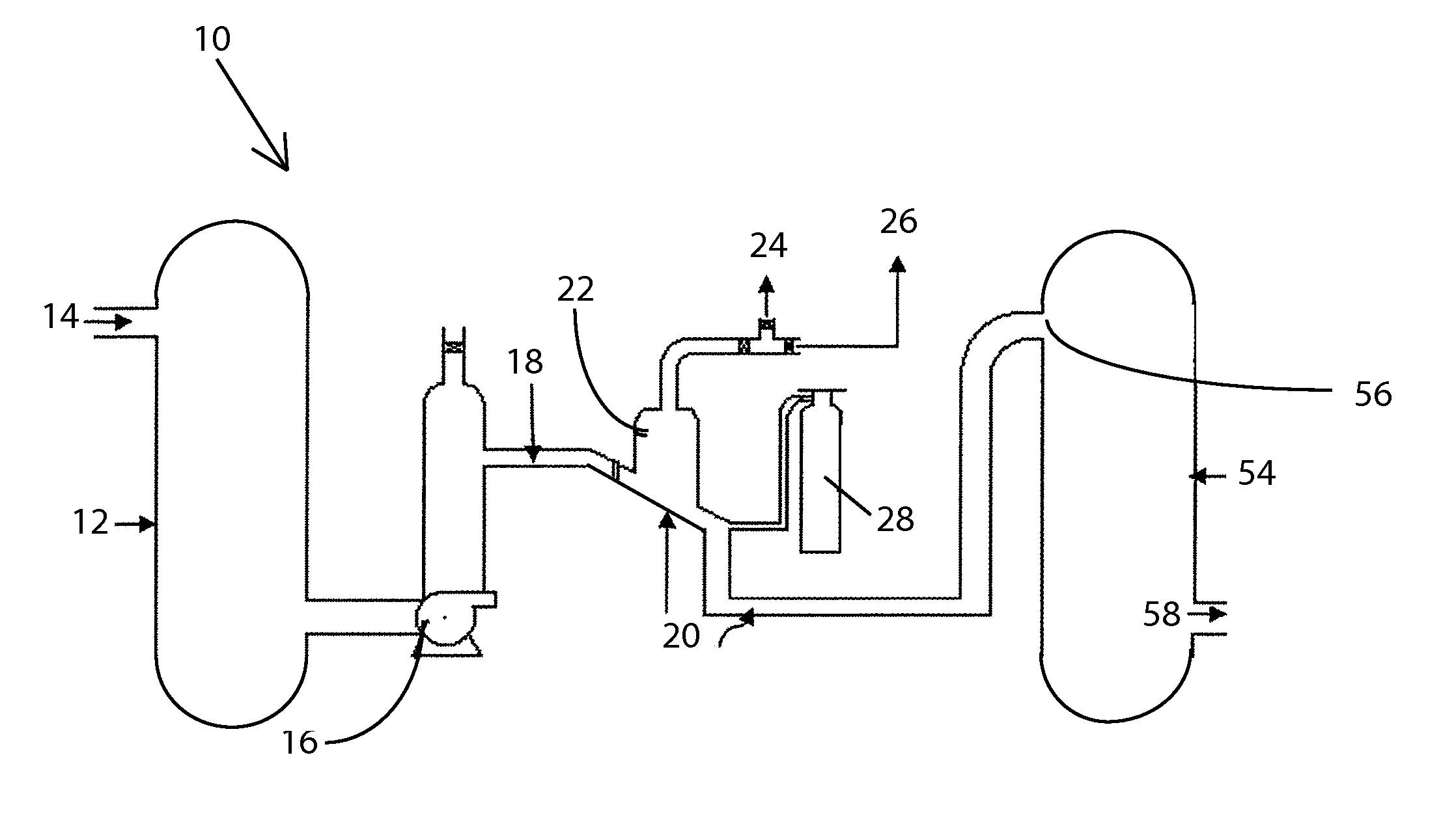
[0039]While the presently disclosed inventive concept(s) is susceptible of various modifications and alternative constructions, certain illustrated embodiments thereof have been shown in the drawings and will be described below in detail. It should be understood, however, that there is no intention to limit the inventive concept(s) to the specific form disclosed, but, on the contrary, the presently disclosed and claimed inventive concept(s) is to cover all modifications, alternative constructions, and equivalents falling within the spirit and scope of the inventive concept(s) as defined in the claims.

[0040]Prior Photolytic CO2 Separation from (MEA)2-CO2

[0041]The disclosed technology discusses separation of CO2 from scrubber of power plant emission streams as an example, but it is to be understood that this application of the technology is merely one example of possible applications, and is currently a preferred embodiment. Patent law requires that at least one preferred embodiment ...


PUM

PropertyMeasurementUnit
widthaaaaaaaaaa
temperatureaaaaaaaaaa
photon energyaaaaaaaaaa

Abstract

A method and apparatus for separating gaseous emission pollutants from a scrubber by using a narrow band of UV light energy emitted from an LED light source. The method includes sweeping the evolved gas away from the flow of liquid containing the pollutant using a non-reactive gas. The pollutant can be CO2, NOx, SOx, or other pollutants. The method can operate on multiple pollutants the gas stream, using different banks of LEDs, specifically tuned for a certain pollutant.

Description

PRIORITY / CROSS-REFERENCE TO RELATED APPLICATIONS[0001]This application claims the benefit of U.S. Provisional Application No. 61 / 335,821, filed Jan. 13, 2010, the disclosure of which is incorporated by reference.TECHNICAL FIELD[0002]The present invention generally relates to methods for removing pollutants from emission streams, and more particularly by use of UV light generated by LED sources in a narrow bandwidth to efficiently separate and remove pollutants of an emission streams from a scrubber.BACKGROUND[0003]Coal-fired plants equipped with the latest thermal process to extract carbon dioxide (CO2) burn 30% more coal than plants that do not extract CO2. CO2 capture requires more coal because it creates a 24% parasitic energy demand by CO2 absorption, desorption, and compression unit operations. Because of this huge added cost, coal-fired plants are resistant to adding CO2 capture technology.[0004]Several international treaties on the Earth's climate at Montreal, Kyoto, and Cope...

Claims


Application Information

Patent Timeline
Patent Type & Authority Applications(United States)
IPC IPC(8): B01D53/14B01D53/75
CPCB01D53/1425B01D53/1456B01D53/1493B01D2252/102B01D2252/20405Y02C10/08B01D2252/20484B01D2257/302B01D2257/404B01D2257/504B01D2259/804B01D2252/20421Y02C20/40
Inventor OMOTOWA, BAMIDELE A.
Owner OMOTOWA BAMIDELE A
Why Eureka
Try Eureka