Energy harvesting system

a technology energy storage, which is applied in the field of energy harvesting system, can solve the problems of solar panel not actually operating at the maximum power point, environmental hazards, and additional costs, and achieve the optimal operation of the energy harvesting system, shorten the time it takes for energy storage, and increase the harvesting efficiency of the energy harvesting unit.

Active Publication Date: 2011-07-14
NATIONAL TSING HUA UNIVERSITY
View PDF3 Cites 31 Cited by
  • Summary
  • Abstract
  • Description
  • Claims
  • Application Information

AI Technical Summary

Benefits of technology

Therefore, the object of the present invention is to provide an energy harvesting system that can eliminate the aforesaid drawbacks of the prior art.
The effects and advantages of the present invention lie in that harvesting efficiency of the energy harvesting unit is increased, that the time it takes for energy storage is shortened, and that the maximum power point can be updated such that optimal operation of the energy harvesting system is ensured regardless of weather conditions and ambient temperature.

Problems solved by technology

However, they are sources of environmental hazards that pose threats to the environment.
1. Additional measuring equipment is required for generating the set of parameters, creating additional costs.
2. Once the set of parameters are loaded into the control circuit, they cannot be changed. However, characteristics of the solar panel may vary according to weather conditions and ambient temperature. Therefore, it is likely that the solar panel does not actually operate at the maximum power point.
3. The set of parameters loaded into the control circuit corresponds to the specific solar panel from which it is measured, such that the control circuit is designed for controlling that specific solar panel only. Therefore, the conventional solar-powered energy harvesting system is not flexible in that once the solar panel is replaced, the control circuit needs to be updated with a new set of parameters that correspond to the replacement solar panel, resulting in extra costs.

Method used


Image

  • Energy harvesting system
  • Energy harvesting system
  • Energy harvesting system

Examples


Embodiment Construction

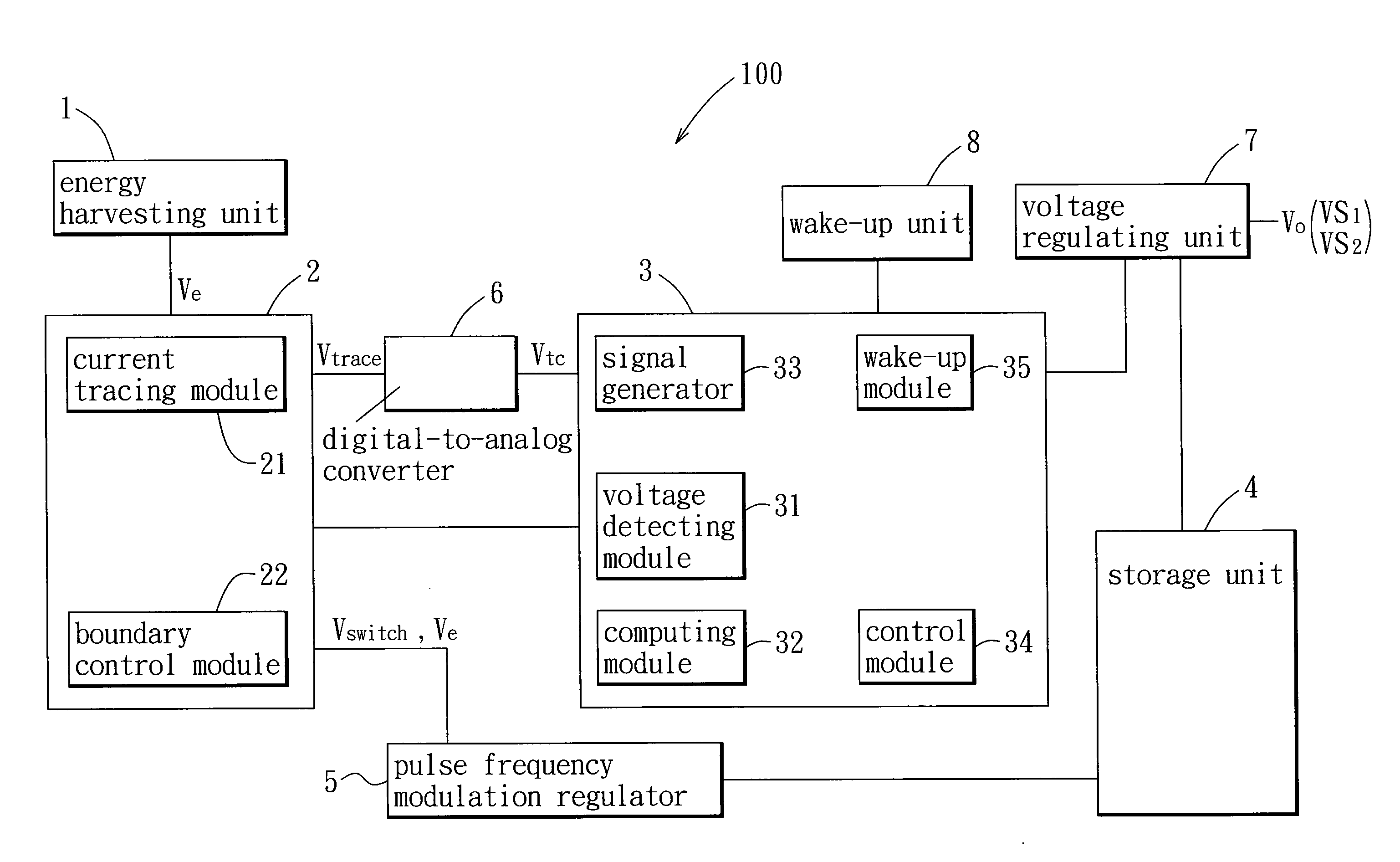
With reference to FIG. 1, the preferred embodiment of an energy harvesting system 100 according to the present invention includes an energy harvesting unit 1, a power point tracking unit 2, a microcontroller 3, a storage unit 4, and a pulse frequency modulation (PFM) regulator 5.

The energy harvesting unit 1 is adapted for converting energy from a natural energy source into an electrical power signal (Ve). While the energy harvesting system 100 is exemplified as a solar-powered energy harvesting system in this embodiment, the present invention is not limited thereto. Accordingly, in this embodiment, the energy harvesting unit 1 includes at least one solar panel that is capable of converting light energy into the electrical power signal (Ve).

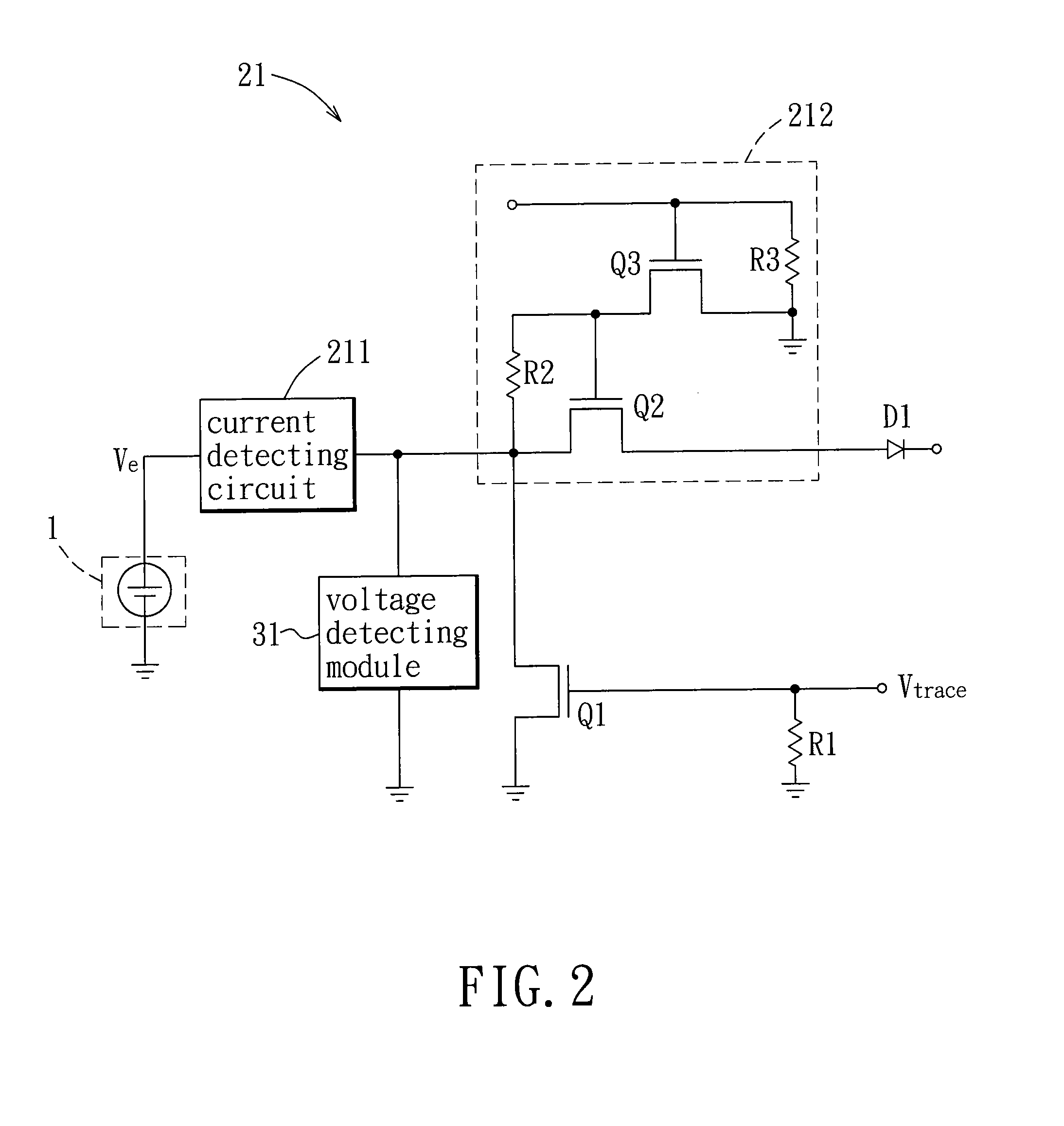
The power point tracking unit 2 includes a current tracing module 21 that is coupled to the energy harvesting unit 1 and that is capable of detecting a current of the electrical power signal (Ve) under each of various loading conditions, and a bou...


PUM


Abstract

An energy harvesting system includes: an energy harvesting unit for converting energy from a natural energy source into an electrical power signal; a power point tracking unit including a current tracing module capable of detecting a current of the electrical power signal, and a boundary control module; a microcontroller including a voltage detecting module capable of detecting a voltage of the electrical power signal, and a computing module for determining a maximum power point with reference to the voltage and the current of the electrical power signal, the boundary control module generating a switch control voltage signal with reference to the maximum power point; a storage unit capable of storing energy; and a pulse frequency modulation regulator for converting the electrical power signal into an intermediate signal with reference to the switch control voltage signal for subsequent storage of energy of the intermediate signal in the storage unit.

Description

CROSS-REFERENCE TO RELATED APPLICATIONThis application claims priority of Taiwanese Application No. 099100899, filed on Jan. 14, 2010.BACKGROUND OF THE INVENTION1. Field of the InventionThe invention relates to an energy harvesting system, more particularly to a solar-powered energy harvesting system.2. Description of the Related ArtFossil fuel, gasoline and natural gas are among the most commonly used energy sources. However, they are sources of environmental hazards that pose threats to the environment. With the decrease of the available amount of these energy sources and with the increase of environmental consciousness, non-polluting and viable energy, such as solar energy, is developing into a major alternative energy source.A conventional solar-powered energy harvesting system includes at least one solar panel and a control circuit. In order to achieve the greatest harvesting efficiency possible, separate measuring equipment is required to obtain a set of parameters in current ...

Claims


Application Information

Patent Timeline
Patent Type & Authority Applications(United States)
IPC IPC(8): G06F1/28G05F3/06H02J3/32
CPCG05F1/67Y02B60/1217G06F1/3203Y02D10/00
Inventor CHEN, CHIEN-YINGCHOU, PAI-HSIANG
Owner NATIONAL TSING HUA UNIVERSITY
Why Eureka
Try Eureka