DC current breaker

Inactive Publication Date: 2011-07-21
ABB (SCHWEIZ) AG
View PDF5 Cites 12 Cited by
  • Summary
  • Abstract
  • Description
  • Claims
  • Application Information

AI Technical Summary

Benefits of technology

[0019]According to another embodiment of the invention said resonance circuit is purely passive. The choice of said relationship of the capacitance to the inductance of the resonance circuit in the device according to the present invention makes it possible to design said resonance circuit to be purely passive and still to be able to obtain a reliable breaking of high DC currents through the interrupter and transfer thereof to said alternative second current path.
[0020]According to another embodiment of the invention the device has only one said interrupter connected in parallel with said resonance circuit. “One interrupter” means in this context an interrupter having only one arc chamber in which an arc is created upon interruption. Such a simple interrupter saving costs may be used in most applications for reliably breaking DC currents being as high as about 5000 A.
[0021]According to another embodiment of the invention the device has two or more said interrupters connected in series, and the series connection of said interrupters is connected in parallel with said resonance circuit. “Two or more said interrupters connected in series” covers the case of two separate interrupters connected in series, but also the case of an interrupter having a plurality of chambers connected in series, so that a plurality of arcs connected in series may be created upon

Problems solved by technology

When a failure occurs in one pole of such a plant the converters of that pole will block and stop the pole current.
The very high inductance between the two paths makes the commutation difficult.
However, known such devices with a passive resonan

Method used


Image

  • DC current breaker
  • DC current breaker
  • DC current breaker

Examples


Example

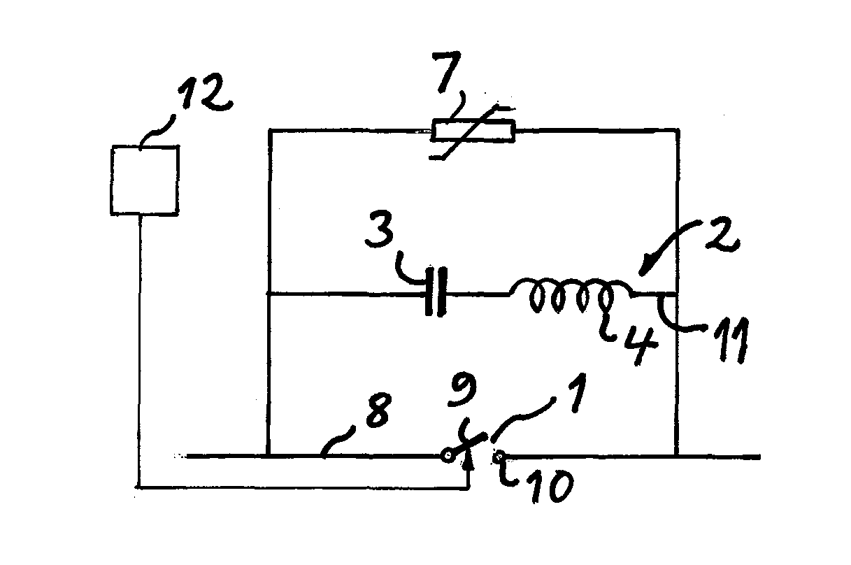
[0035]FIG. 5 illustrates a device according to a first embodiment of the present invention comprising one single interrupter 1 to be arranged in a first current path 8 and having contacts 9, 10 movable with respect to each other from a closing to an opening position of the interrupter for breaking a current flowing therethrough. The device has also a resonance circuit 2 connected in parallel with the interrupter and comprising a capacitor 3 and an inductance 4 formed solely by the self inductance of a conductor 11 used to connect the capacitor in parallel with the interrupter. The series connection of the capacitor and the inductance is configured to create an oscillating current superimposed on a DC current through the interrupter for breaking at zero-crossing of the current through the interrupter enabling breaking of this current when the contacts 9, 10 are moved apart. The device has also a surge arrester 7 connected in parallel with the resonance circuit and configured to start...

Example

[0038]FIG. 6 illustrates a device according to a second embodiment of the invention differing from the embodiment shown in FIG. 5 only by the arrangement of two interrupters 1a, 1b in series. This series connection shall be understood as a series connection of two arcs formed upon separation of two couples of contacts when breaking a current. Thus, it may be a question of two separate interrupters connected in series or an interrupter having two chambers with contacts connected in series. This embodiment results in a higher arc voltage, a higher probability to create a voltage step that initiates the current oscillation and gives an increased withstand capability during the transient recovery phase with respect to the embodiment shown in FIG. 5. Series connection of the complete unit can also be possible as well as the series connection shown in FIG. 6.

Example

[0039]A third embodiment of a device according to the present invention is shown in FIG. 7, and this differs from the embodiment shown in FIG. 5 by the fact that the resonance circuit comprises a switch 6 connected in series with the capacitor and the inductance and configured to be open when the interrupter is in a closed conducting state. The control means 12 is adapted to control the switch 6 to close and by that to close the resonance circuit with a delay, such as 15 ms after, with respect to a contact separation during an opening of the interrupter. This makes it possible to create a rather well defined voltage step that initiates the current oscillation in the resonance circuit. It is pointed out that the embodiment shown in FIG. 7 may of course have more than one interrupter or arcs created upon opening connected in series.

[0040]The sequence of breaking a DC current flowing in a first current path through an interrupter in a device according to the present invention and trans...


PUM

PropertyMeasurementUnit
Electrical inductanceaaaaaaaaaa

Abstract

A device for breaking DC currents exceeding 2500 A has a resonance circuit connected in parallel with an interrupter and a surge arrester connected in parallel with the resonance circuit. The resonance circuit has a series connection of a capacitor and an inductance. The relationship of the capacitance in μF to the inductance in μH of the resonance circuit is ≧1.

Description

TECHNICAL FIELD OF THE INVENTION AND BACKGROUND ART[0001]The present invention relates to a device configured to break DC currents exceeding 2500 A flowing in a first current path and transfer said DC currents to an alternative second current path, said device comprising:[0002]at least one interrupter to be arranged in said first current path and having contacts movable with respect to each other from a closing to an opening position of the interrupter for breaking a current flowing therethrough,[0003]a resonance circuit connected in parallel with said interrupter and comprising a capacitor and an inductance connected in series and configured to create an oscillating current superimposed on said DC current for creating a zero-crossing of the current flowing through the interrupter, thereby enabling breaking of this current when said contacts are moved apart, and[0004]a surge arrester connected in parallel with said resonance circuit and configured to start to conduct when the voltag...

Claims


Application Information

Patent Timeline
IPC IPC(8): H02B1/24
CPCH01H33/596Y02E60/60
Inventor ASTROM, URBANLILJESTRAND, LARSLESCALE, VICTORBACKMAN, MAGNUS
Owner ABB (SCHWEIZ) AG
Why Eureka
Try Eureka