Switching control circuit and switching power-supply apparatus

a control circuit and power supply technology, applied in the direction of power conversion systems, instruments, dc-dc conversion, etc., can solve the problems of increasing increasing the unit price of the ic, and limiting the number of functions that can be provided, so as to reduce the number of terminals of the ic, reduce the size of the ic, and reduce the cost

Active Publication Date: 2011-07-21
MURATA MFG CO LTD
View PDF21 Cites 66 Cited by
  • Summary
  • Abstract
  • Description
  • Claims
  • Application Information

AI Technical Summary

Benefits of technology

[0017]To overcome the problems described above, preferred embodiments of the present invention provide a switching control circuit a number of terminals that is not increased, and a small-size and low-cost switching power-supply apparatus, by increasing a number of selectable functions, as compared to the known system in which the parameter / mode is set in accordance with a difference in the rate of increase in the charging voltage of the capacitor, and enabling an existing terminal to have an additional function (i.e., to have a hidden function).
[0050]According to various preferred embodiments of the present invention, it is possible to use an existing terminal to set another function without affecting the function of the normal operation of the existing terminal. Accordingly, it is possible to reduce the number of terminals of an IC, reduce the size of the IC, and reduce the cost. In addition, configuring the IC to have multiple functions enables it to be applied to power supplies with a wide range of specifications and for a wide variety of applications.

Problems solved by technology

An increase in the number of terminals results in an increased package size of the switching control IC, which leads to an increase in the unit price of the IC.
When the number of terminals for a switching control IC is limited, the number of functions that can be provided are also limited.
In this case, there are problems in that the number of variants of the ICs increases, not only the manufacturing process but also the IC management becomes complicated, and consequently the unit price of the ICs increases.
However, recently, even for small-sized switching control circuits, the number of required functions has been increasing.
In addition, since only the capacitor is used to set the parameter / mode, the selection function is severely restricted.

Method used


Image

  • Switching control circuit and switching power-supply apparatus
  • Switching control circuit and switching power-supply apparatus
  • Switching control circuit and switching power-supply apparatus

Examples


first preferred embodiment

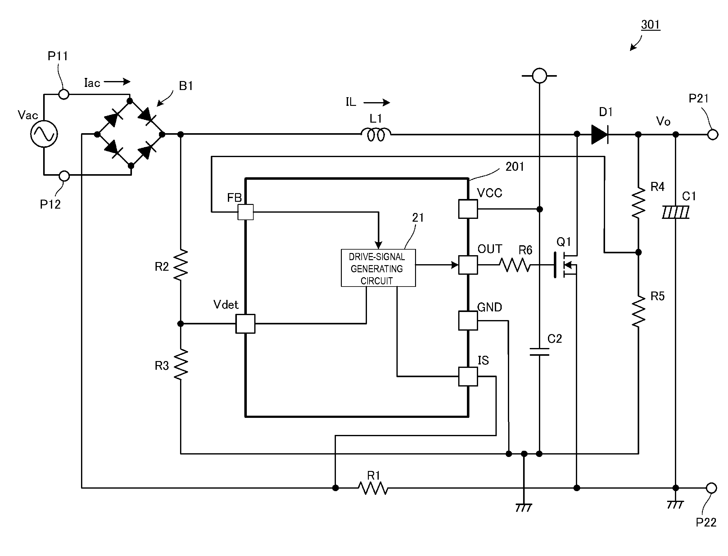
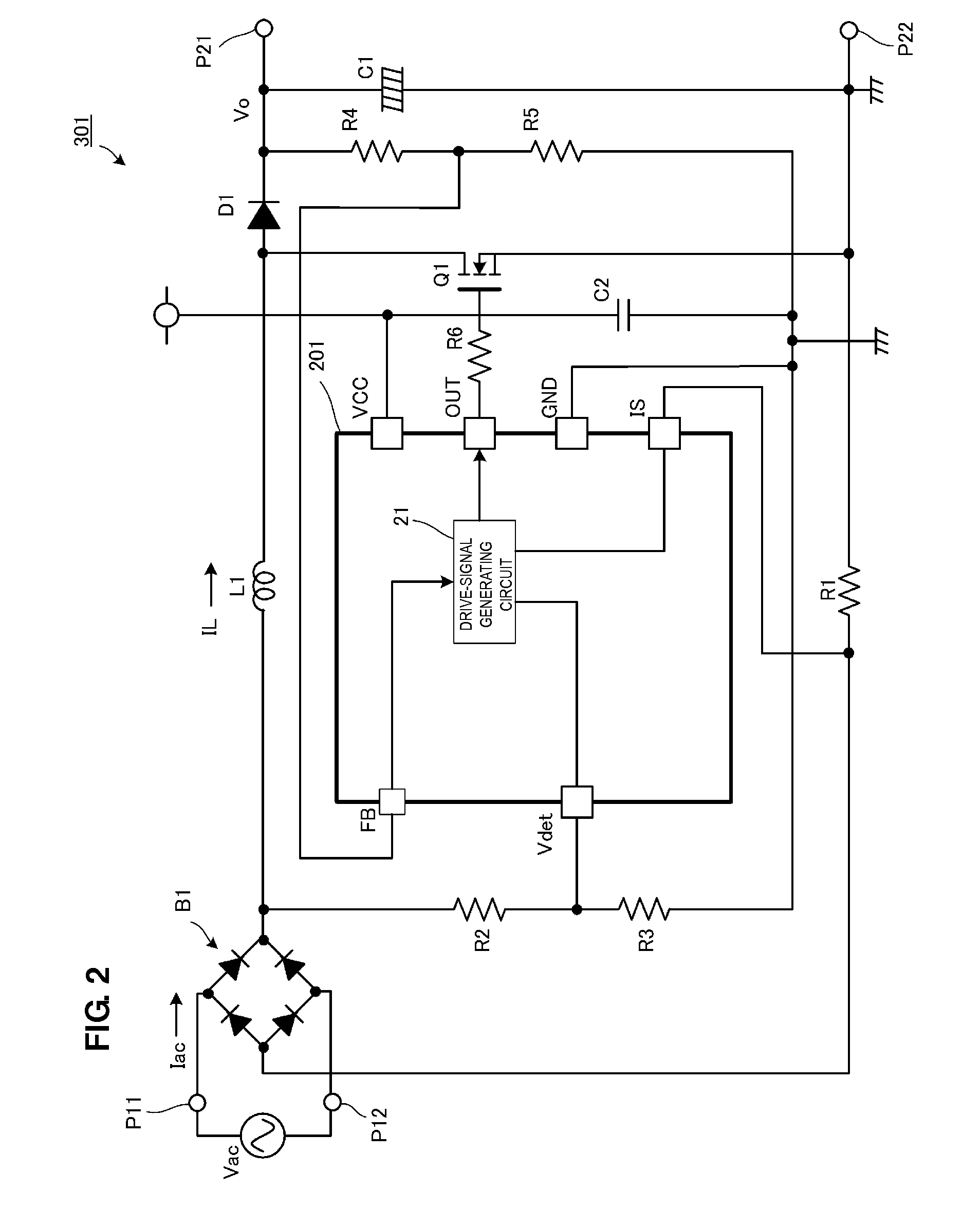
[0075]FIG. 2 is a circuit diagram of a PFC (power-factor corrected) converter 301 according to a first preferred embodiment of the present invention.

[0076]The PFC converter 301 is one example of a switching control device according to a preferred embodiment of the present invention and includes a switching control integrated circuit (IC) 201 corresponding to the switching control circuit of a preferred embodiment of the present invention.

[0077]The PFC converter 301 includes input terminals P11 and P12 and output terminals P21 and P22. An alternating-current (AC) input power supply Vac, which is commercial AC power supply, is preferably input to the input terminals P11 and P12 and a load circuit is connected to the output terminals P21 and P22.

[0078]Examples of the load circuit include a DC-DC converter or a circuit of electronic equipment that receives a power supply through a DC-DC converter.

[0079]An input stage of the PFC converter 301 includes a diode bridge B1, which functions a...

second preferred embodiment

[0094]FIG. 5 is a circuit diagram of a DC-DC converter 302 according to a second preferred embodiment of the present invention.

[0095]The DC-DC converter 302 is one example of the switching control device according to a preferred embodiment of the present invention and includes a switching control IC 202 corresponding to the switching control circuit according to a preferred embodiment of the present invention.

[0096]A voltage of the DC input power supply Vi is input between an input terminal PI(+) and an input terminal PI(G) of the DC-DC converter 302. A load is connected between an output terminal PO(+) and an output terminal PO(G) of the DC-DC converter 302. A predetermined DC voltage is output to the load.

[0097]A first series circuit including a capacitor Cr, an inductor Lr, a primary winding np of a transformer T, a first switching element Q1, and a current-detection resistor R7 that are connected in series is preferably provided between the input terminal PI(+) and the input ter...

third preferred embodiment

[0125]FIG. 9 is a block diagram showing an internal configuration of a switching control IC 200 included in a DC-DC converter according to a third preferred embodiment of the present invention.

[0126]In FIG. 9, when the standby mode is on, a maximum-blanking-frequency setting circuit 230 preferably sets a maximum blanking frequency in accordance with a voltage of a feedback terminal FB (a hidden function of ON / OFF of the standby mode is accomplished at a ZT terminal described below). The maximum-blanking-frequency setting circuit 230 also reads the voltage of the feedback terminal FB when the converter is started. Now, a description will be given of a case in which the read voltage value is less than or equal to a predetermined value.

[0127]Based on the voltage at the ZT terminal, a ZT-voltage detection circuit 226 detects that the voltage across the drive winding nb of the transformer T is reversed and issues a trigger to a one-shot circuit 240. The maximum-blanking-frequency setting...


PUM


Abstract

A switching power-supply apparatus and a switching power supply circuit in which a feedback signal is input from a feedback circuit to a feedback terminal of a switching control IC includes a capacitor and a Zener diode connected between the feedback terminal and a ground terminal. The Zener diode is a selectively connected external circuit. A voltage of the feedback terminal during an overcurrent operation changes depending on whether or not the external circuit is present. A return / latch determination circuit detects the voltage of the feedback terminal to switch between an automatic return system and a latch system in an overcurrent operation state.

Description

BACKGROUND OF THE INVENTION[0001]1. Field of the Invention[0002]The present invention relates to a switching control circuit integrated into an IC (integrated circuit), and also relates to a switching power-supply apparatus including the switching control circuit.[0003]2. Description of the Related Art[0004]Typically, a switching control IC in a switching power-supply apparatus includes a circuit arranged to provide various functions for, for example, output control, startup operation, overcurrent protection operation, overvoltage protection operation, standby operation, and power-factor correction operation. The number of functions is increased to improve the functions of the switching control ICs.[0005]In order to set the functions of a switching control IC so that they correspond to operation specifications of an application, multiple terminals arranged to interface with external circuits are required for the respective functions. Thus, when the number of functions increases, the...

Claims


Application Information

Patent Timeline
Patent Type & Authority Applications(United States)
IPC IPC(8): G05F1/46
CPCH02M3/3376H02M3/33515
Inventor HOSOTANI, TATSUYA
Owner MURATA MFG CO LTD
Why Eureka
Try Eureka