High-efficiency all-digital transmitter

Inactive Publication Date: 2011-07-21
PANASONIC CORP
View PDF5 Cites 7 Cited by
  • Summary
  • Abstract
  • Description
  • Claims
  • Application Information

AI Technical Summary

Benefits of technology

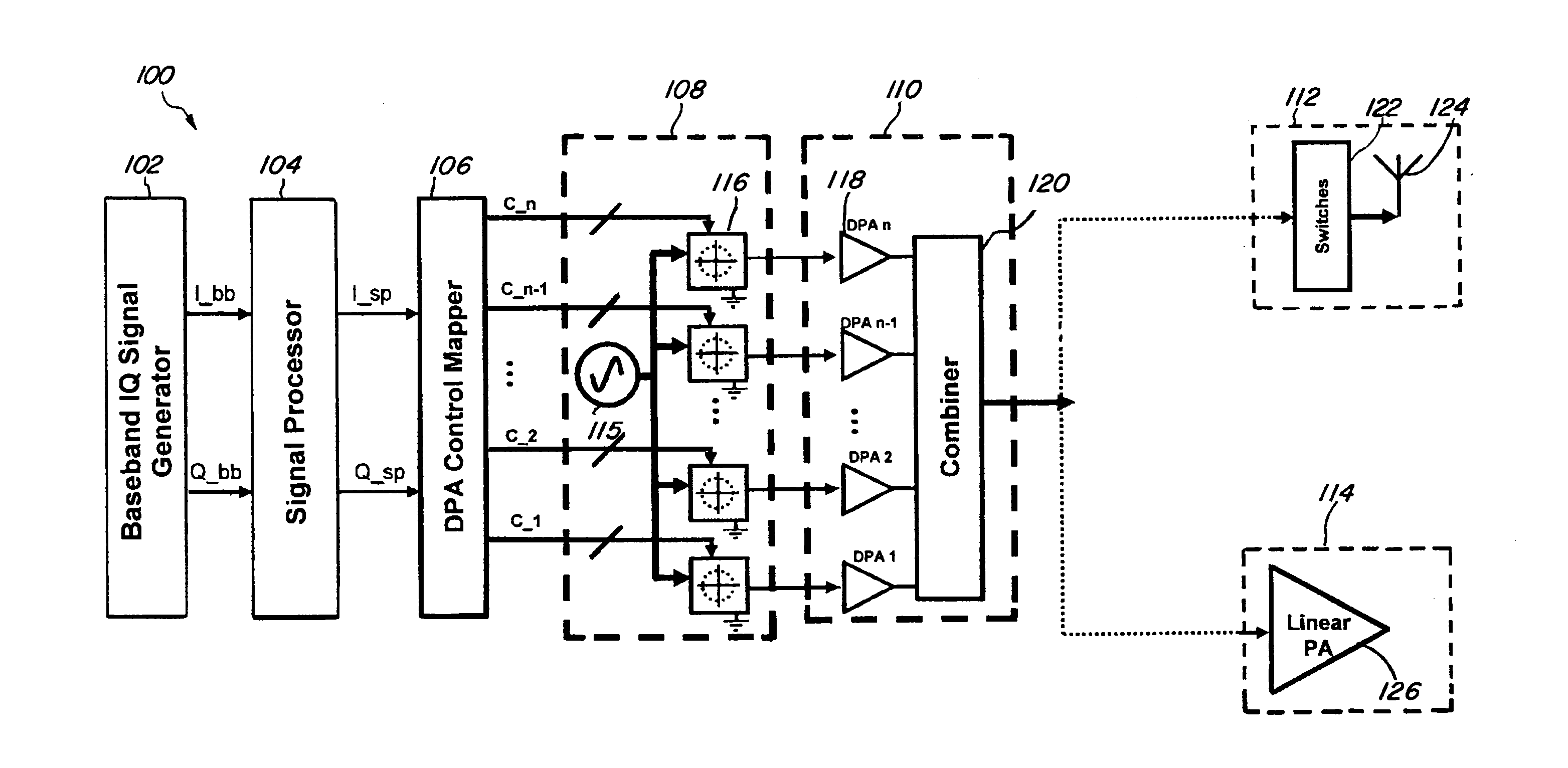
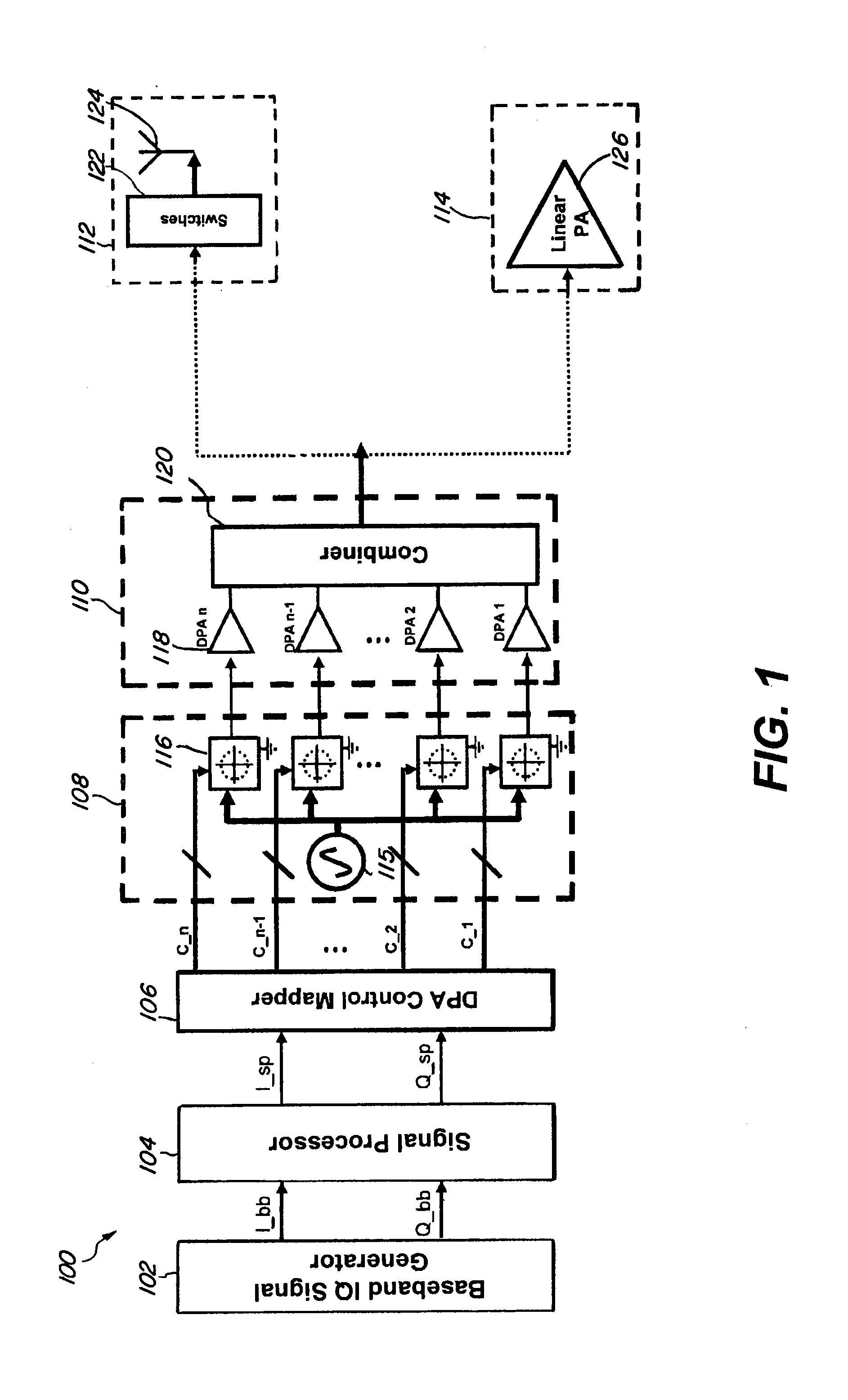
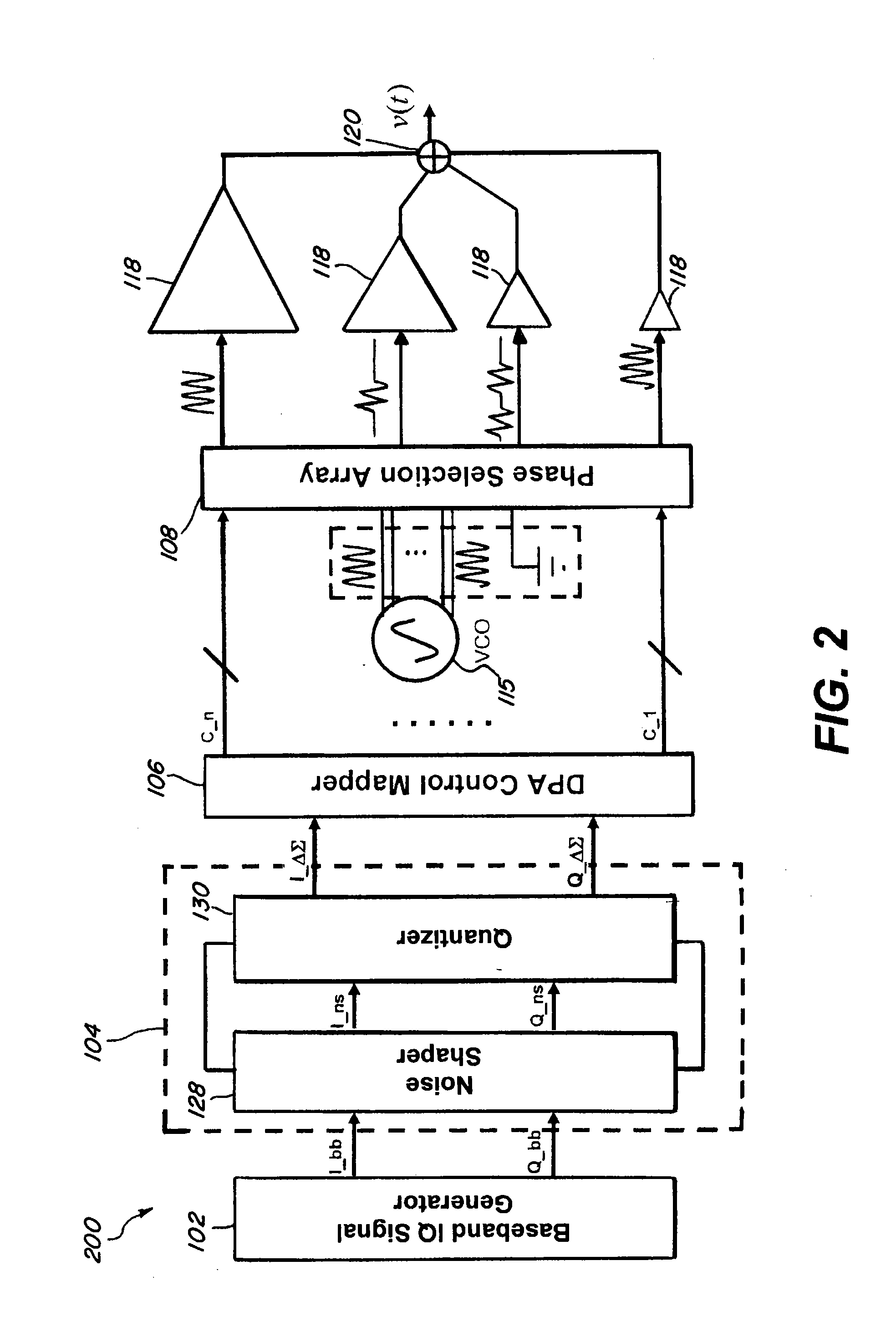
[0006]The present invention is directed to a low cost high-efficiency all-digital transmitter which uses all-digital power amplifiers. The present invention uses various mapping techniques to generate an output signal, which substantially reproduces a baseband signal at a carrier frequency. The various mapping techniques can be, for example, equal-weight mapping, binary-weight mapping, arbitrary weight mapping, and / or grid mapping. In the present invention, a baseband signal generator generates a baseband signal which is quantized by a signal processor using a quantization map specific to the selected mapping technique. The digital power amplifier (“DPA”) control mapper outputs control signals to a phase selection array using the quantized signal and its corresponding entry in a quantization table. The quantization table corresponds to the quantization map and is also specific to the selected mapping technique. The phase selector array comprises multiple phase selectors, with each phase selector receiving one of the control signals. Each of the phase selectors either outputs a waveform at a carrier frequency with a phase corresponding to the control signals or outputs an inactive signal. The possible phases for the phase selectors can be increased to reduce the noise for the output signal.
[0007]A DPA array comprises a plurality of DPAs with each of the DPAs having an assigned weight according to the mapping technique. The number of phase selectors and the number of DPAs can correspond in a one to one manner. Increasing the number of phase selectors and DPAs used can reduce the noise of output signal. Each of the DPAs receives one of the waveforms from the phase selectors and outputs a power signal according to the weight of the DPA and the phase of the received waveform. The combined power signal substantially reproduces the baseband signal at the carrier frequency. Thus, the present invention can reproduce the baseband signal at the carrier frequency without using supply modulation and without mismatch problems. This can reduce the production cost of the transmitters.

Problems solved by technology

The AM path and the PM path have delay mismatch problems to the power amplifier, which can make it difficult to build a supply modulator required for the AM path.
Thus, it is difficult to implement a supply modulator, which has high bandwidth, low noise, and high efficiency.
Therefore, production of the conventional high efficiency transmitters is costly.

Method used


Image

  • High-efficiency all-digital transmitter
  • High-efficiency all-digital transmitter
  • High-efficiency all-digital transmitter

Examples


Embodiment Construction

[0060]Reference will now be made in detail to the preferred embodiments of the invention which set forth the best modes contemplated to carry out the invention, examples of which are illustrated in the accompanying drawings. While the invention will be described in conjunction with the preferred embodiments, it will be understood that they are not intended to limit the invention to these embodiments. On the contrary, the invention is intended to cover alternatives, modifications and equivalents, which may be included within the spirit and scope of the invention as defined by the appended claims. Furthermore, in the following detailed description of the present invention, numerous specific details are set forth in order to provide a thorough understanding of the present invention. However, it will be obvious to one of ordinary skill in the art that the present invention may be practiced without these specific details. In other instances, well known methods, procedures, components, mo...


PUM


Abstract

A low cost high-efficiency all-digital transmitter using all-digital power amplifiers (“DPA”) and various mapping techniques to generate an output signal, which substantially reproduces a baseband signal at a carrier frequency. A baseband signal generator generates a baseband signal which is quantized by a signal processor using a quantization map. A DPA control mapper outputs control signals to phase selectors using the quantized signal and a quantization table. Each phase selector receives one of the control signals and outputs a waveform at a carrier frequency with a phase corresponding to the control signals, or an inactive signal. Each DPA in a DPA array has an assigned weight, receives one of the waveforms from the phase selectors, and outputs a power signal according to the weight of the DPA and the phase of the received waveform. The combined power signal substantially reproduces the baseband signal at the carrier frequency.

Description

BACKGROUND[0001]1. Field of the Invention[0002]The present invention relates to a high-efficiency all-digital transmitter.[0003]2. Description of Related Art[0004]High-efficiency transmitters are preferred in wireless communications because they allow longer talk time and / or longer battery life. Conventional high-efficiency transmitter may use, for example, polar modulation schemes. However, polar domain signal processing and supply modulation in the polar modulation scheme use two separate paths to a power amplifier, an amplitude modulation (“AM”) path and a phase modulation (“PM”) path. The AM path and the PM path have delay mismatch problems to the power amplifier, which can make it difficult to build a supply modulator required for the AM path. Thus, it is difficult to implement a supply modulator, which has high bandwidth, low noise, and high efficiency. Therefore, production of the conventional high efficiency transmitters is costly.[0005]Thus, there is a need for a low cost h...

Claims


Application Information

Patent Timeline
IPC IPC(8): H04L27/12
CPCH04L27/36H03D7/165
Inventor WANG, HUAMATSUURA, TORUIE GRAND DE MERCEY, GREGOIRELIANG, PAUL CHENG-POTAKINAMI, KOJIBOOTH, RICHARD W. D.
Owner PANASONIC CORP
Why Eureka
Try Eureka