Technique for selectively changing dispersion in optical communication channels

a technology of optical communication channel and dispersion, applied in the field of selectively changing dispersion in optical communication channel, can solve the problem that no prior art device proposes a simple economic structure, and achieve the effect of maximising the transmission quality

Inactive Publication Date: 2011-07-21
ECE TELECOM LTD
View PDF8 Cites 14 Cited by
  • Summary
  • Abstract
  • Description
  • Claims
  • Application Information

AI Technical Summary

Benefits of technology

[0004]There is a long felt need in providing a unite device (node) for optical networks such as wave division multiplexing (WDM) ones, which would allow selectively adjusting chromatic dispersion in a plurality of communication optical c...

Problems solved by technology

None of the prior art devices proposes a simple economic structur...

Method used


Image

  • Technique for selectively changing dispersion in optical communication channels
  • Technique for selectively changing dispersion in optical communication channels
  • Technique for selectively changing dispersion in optical communication channels

Examples


embodiment 40

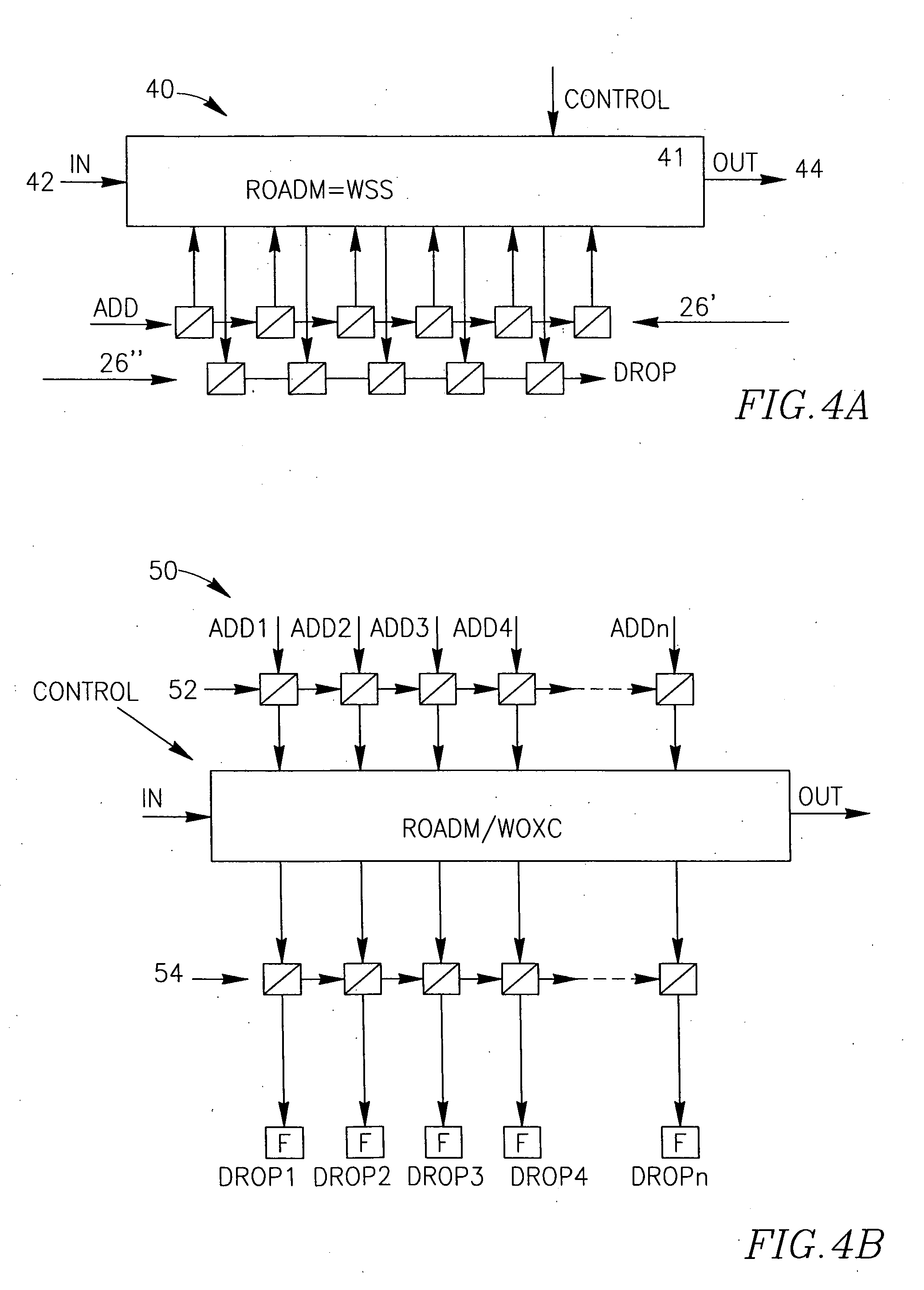
[0073]FIG. 4 A illustrates one hybrid embodiment 40 of the RWSDCD. The hybrid RWSDCD comprises a wavelength selecting unit (WSU) 41 being an ROADM based Wavelength Selective Switch WSS. The WSU 41 may, for example, comprise a matrix of two or more structures similar to the WSS 21, where at least one WSS utilizes its local I / O ports as input ports, and at least one—as output ports. Alternatively, the WSU 41 may be based on a Wavelength Optical Cross Connect WOXC.

[0074]The ROADM 41 has a common input line 42 and a common output (“through”) line 44. The ROADM 41 is equipped with a dispersion compensating cascade comprising two DCU chains 26′ and 26″, one of the chains being connected to the input local ports an the other chain—to the output local ports.

[0075]The optical channels to be added to ROADM 41 can be inputted at the input ADD of the chain 26′, any specific one of these channels may pass as many of the DCUs in the chain and enter the ROADM at the I / O (input) port assigned f...

embodiment 60

[0078]FIG. 5 illustrates a schematic embodiment 60 of the RWSDCD, where the Wavelength Selecting unit is implemented as a Wavelength Router 62 controllable by tuning tunable lasers TL1-TLN (or Wavelength Converting blocks WC1-WCN) of the incoming optical channels (in this example of the router, N=4). In case of the tunable lasers TL, the RWSDCD performs pre-compensation of dispersion in the optical channels, based on information concerning the remote west-side portion of the network (not shown), which can be obtained, say, from a Network Management System. In case of the wavelength convertors WC, the optical channels indicated by four dashed lines may arrive from an east-side portion of the network (possibly, upon “opening the combined channel by a demultiplexer), and the RWSDCD will perform compensation of the real accumulated dispersion per channel. It is understood that a hybrid embodiment is possible, when some channels are input via tunable lasers and some—via wavelength conver...


PUM


Abstract

A reconfigurable wavelength selective dispersion compensation device RWSDCD for selective compensation of dispersion in optical channels having different wavelengths. The RWSDCD comprises a controllable wavelength selective unit WSU having a plurality of local, wavelength related input/output (I/O) ports. The RWDSD also comprises a dispersion compensation cascade comprising at least one chain of successively connected dispersion compensation units DCUs, wherein one or more of the DCUs in the chain are respectively connectable to one or more of the local I/O ports. The RWSDCD outputs one or more of the incoming optical channels upon selectively compensating chromatic dispersion in them, by controllably passing these channels via one or more DCUs of the dispersion compensation cascade.

Description

FIELD OF THE INVENTION[0001]The present invention relates to equipment for selectively changing / adjusting chromatic dispersion in different optical channels carrying information in optical networks.BACKGROUND OF THE INVENTION[0002]US2005008287A describes a modular dispersion compensator to compensate for dispersion of a WDM optical signal. The method begins by directing a WDM optical signal having a prescribed bandwidth to a first dispersion compensating element and substantially compensating, with the first dispersion compensating element, each wavelength in the WDM optical signal for dispersion at a prescribed wavelength within a first sub-band of the prescribed bandwidth. The method continues by directing to a second dispersion compensating element wavelengths received from the first dispersion compensating element outside the first sub-band and substantially compensating, with the second dispersion compensating element, each wavelength received from the first dispersion compensa...

Claims


Application Information

Patent Timeline
IPC IPC(8): H04J14/02H04B10/02H04B10/2513
CPCH04B10/25133
Inventor MAHLAB, URILEVY, AVI
Owner ECE TELECOM LTD
Why Eureka
Try Eureka