
Continuously Variable Planet Gear Transmission

a transmission system and planet technology, applied in the direction of differential gearings, belts/chains/gearings, portability lifting, etc., can solve the problems of parasitic losses, conventional power plants do not operate at their peak efficiency, and the use of previously existing transmissions is quite inefficient, etc., to achieve low weight and loss, low power consumption, and high performance

Inactive Publication Date: 2011-07-21
CAMPBELL JOSHUA
View PDF0 Cites 23 Cited by
  • Summary
  • Abstract
  • Description
  • Claims
  • Application Information

AI Technical Summary

Benefits of technology

The invention is a transmission system for a vehicle that combines a continuously variable transmission and a planetary gear set. The system includes a drive pulley, a driven pulley, and a belt that connects the two pulleys. The system also includes a controller that can adjust the pitch radius of the belt in contact with the pulleys to achieve a desired gear ratio. The system can be used in a vehicle that has a pair of electric motors and a pair of wheels, and the controller can independently adjust the pitch ratio of the belt in contact with each motor to provide precise control over the vehicle's speed and power output. The technical effect of the invention is to provide a more efficient and effective transmission system for electric vehicles.

Problems solved by technology

With the new development of series drive hybrid systems the use of previously existing transmissions can be quite inefficient due to motor characteristics and can incur parasitic losses such as rotating mass and weight.
These inefficiencies are principally due to the fact that series drive hybrids behave quite differently from other power plants and require the development of the energy transmissions systems capable of doing the same.
Conventional power plants do not operate at their peak efficiency with the transmission system shifting constantly to deliver adequate power.
A series drive electric hybrid uses only the electric motors to drive the vehicle forward, and with the characteristics of the electric motor this shifting characteristic of some types of conventional transmissions creates losses due to rotating mass and variability in the operating point of the motor.

Method used


Image

  • Continuously Variable Planet Gear Transmission
  • Continuously Variable Planet Gear Transmission
  • Continuously Variable Planet Gear Transmission

Examples


Embodiment Construction

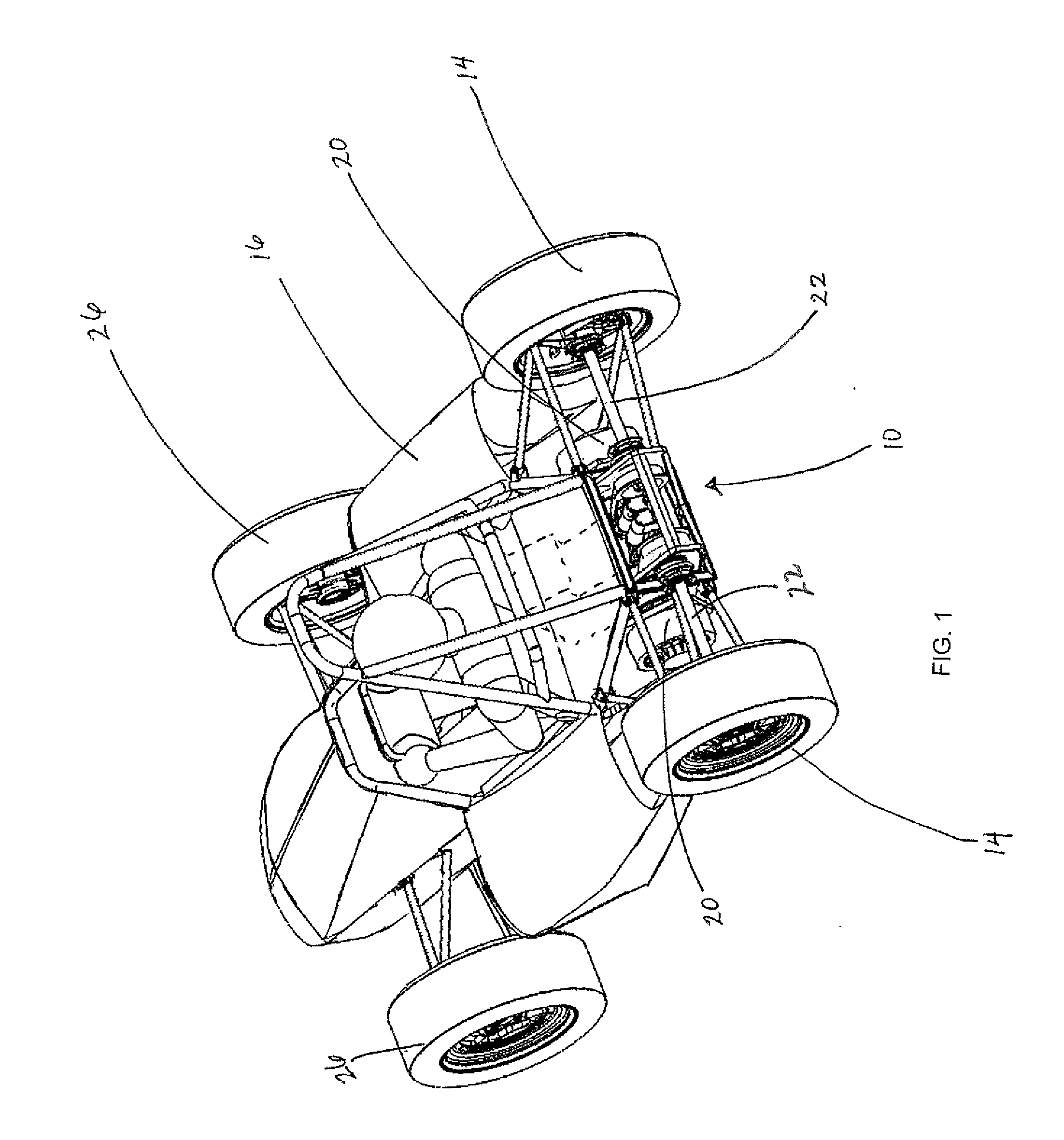
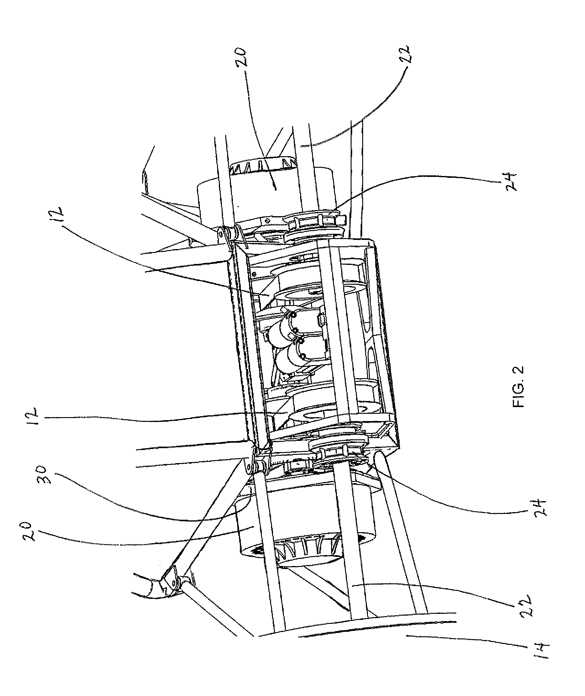
[0047]Referring to the accompanying Figures, there is illustrated a continuously variable planet gear transmission system generally indicated by reference numeral 10. The system10 generally comprises a pair of continuously variable transmissions 12 associated with respective ones of a pair of laterally opposed drive wheels 14 of a vehicle 16.

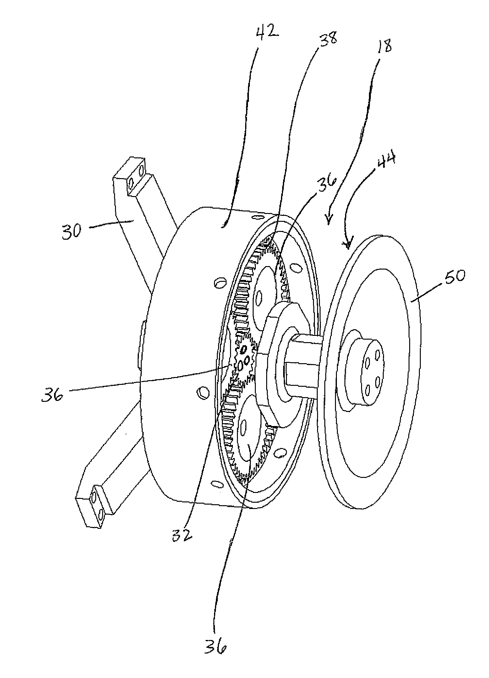
[0048]In the illustrated embodiment, the two drive wheels 14 comprise laterally opposed rear wheels of the vehicle. Each continuously variable transmission (CVT) 12 incorporates an integral planetary gear set 18 so that the CVT together with the gear set 18 controls power transmission from a respective one of two electric motors 20 on the vehicle to respective ones of the two drive wheels 14.

[0049]The vehicle 16 further comprises a frame supported on the two rear drive wheels 14 by respective suspension assemblies such that each wheel includes a wheel axle 22 which is coupled between variable angle couplings 24 at opposed ends thereof in which t...


PUM


Abstract

A transmission system for a vehicle with an electric motor includes a continuously variable transmission having a drive pulley, a driven pulley connected to one wheel of the vehicle, and a belt operatively connected between the drive pulley and the driven pulley such that a pitch radius of the belt in contact with each pulley is variable. The transmission system further includes a planetary gear set having a sun gear connected to the output of the motor, a ring gear connected to the drive pulley, and a planet gear operatively connected between the sun gear and the ring gear. The planet gear is rotatable about a respective planet gear axis which is fixed in position relative to the sun gear axis such that the planetary gear set is arranged to be operable at a fixed gear reduction.

Description

[0001]This application claims the benefit under 35 USC 119(e) from U.S. Provisional application No. 61 / 297,043, filed Jan. 21, 2010.FIELD OF THE INVENTION[0002]The present invention relates to a continuously variable planet gear transmission system comprising a belt type continuously variable transmission in connection between an electric motor and a respective driven wheel and an integral planetary gear set providing a fixed gear reduction from the electric motor to the continuously variable transmission, and more particularly, the present invention relates to a pair of continuously variable planet gear transmissions operable independently of one another between respective electric motors and respective laterally opposed drive wheels of a vehicle.BACKGROUND[0003]With evolving demands for alternative energies, new approaches need to be taken in developing the efficient transmission of these energies.[0004]To some extent, hybrid drive technologies are only as good as the systems tran...

Claims


Application Information

Patent Timeline
Patent Type & Authority Applications(United States)
IPC IPC(8): F16H9/26F16H55/52
CPCB60K7/0007B60K17/08B60K2007/0046B60K2007/0061F16H2009/163F16H9/18F16H37/022F16H55/56B60Y2200/86
Inventor CAMPBELL, JOSHUA
Owner CAMPBELL JOSHUA
Learn More