Superconducting fault current-limiter with variable shunt impedance

Active Publication Date: 2011-07-21
SUPERPOWER INC
View PDF14 Cites 20 Cited by
  • Summary
  • Abstract
  • Description
  • Claims
  • Application Information

AI Technical Summary

Benefits of technology

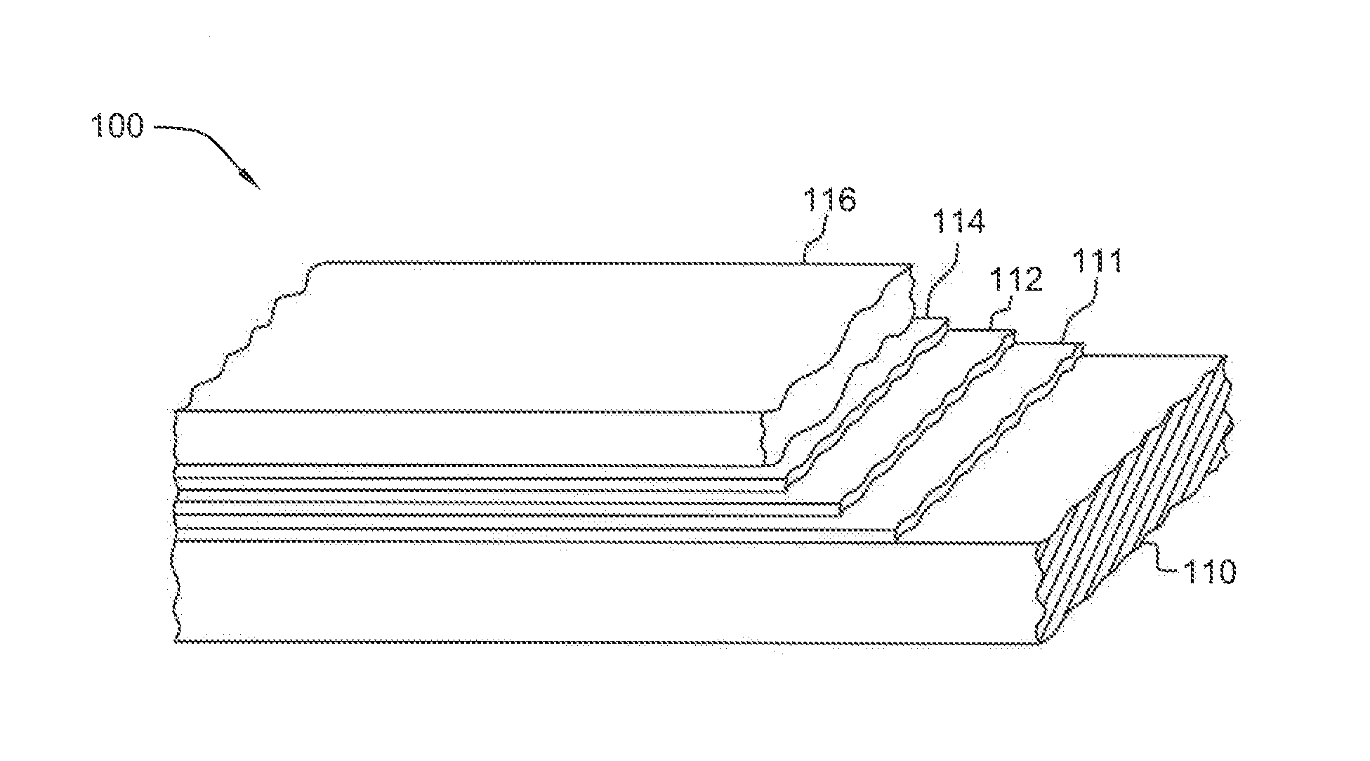
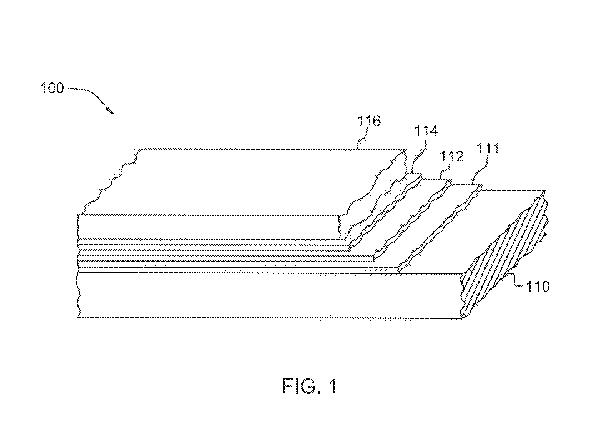
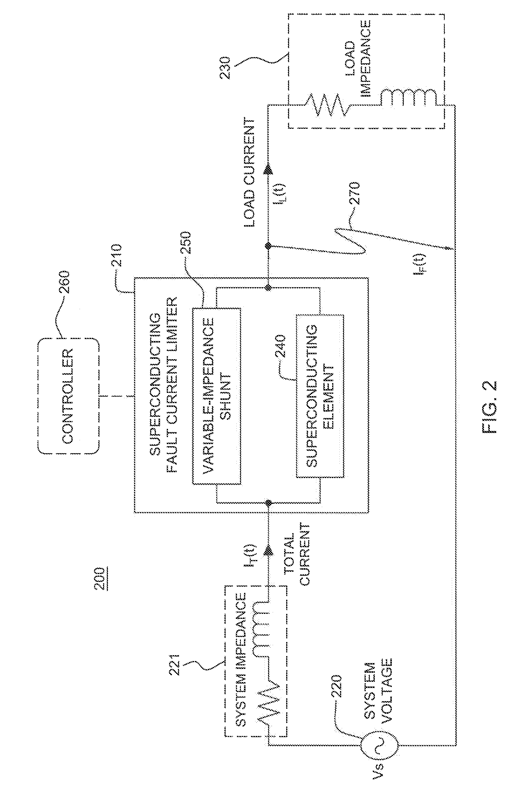
[0009]Briefly summarized, in one aspect, the present invention comprises a superconducting fault current-limiter which includes a superconducting element and at least one variable-impedance shunt electrically coupled in parallel with the superconducting element. The superconducting element is configured to at least partially resistively or inductively limit a fault current passing therethrough, and the at least one variable-impedance shunt is configured to present a first impedance during a superconducting state of the superconducting element and a second impedance during a recovery transition of the superconducting element from a normal resistive state to the superconducti

Problems solved by technology

Current-limiting devices are critical in electric power transmission and distribution systems.
For various reasons, such as a lightning strike, a short circuit condition can develop in a section of a power grid causing a sharp surge in current.
If this surge of current, which is often referred to as fault current, exceeds the protective capabilities of the switchgear equipment deployed throughout the grid system, it could cause catastrophic damage to the grid equipment and the customer loads that are connected to the system.
Essentially, at the initial stage of quenching by the curre

Method used


Image

  • Superconducting fault current-limiter with variable shunt impedance
  • Superconducting fault current-limiter with variable shunt impedance
  • Superconducting fault current-limiter with variable shunt impedance

Examples


Embodiment Construction

[0034]Various prior applications and patents focus on a quench triggering mechanism for a superconducting fault current-limiter. For example, reference U.S. Pat. Nos. 6,809,910, 6,958,893, 7,283,339, and 7,440,244, the entirety of each of which is hereby incorporated herein by reference. In contrast, the present invention is directed to a superconducting fault current-limiter with enhanced recovery of the superconducting element under load subsequent to limiting of a fault current.

[0035]Certain superconducting fault current-limiter topologies employ a parallel impedance reactance to further limit a fault current and allow a certain amount of current to flow when the superconducting element changes its impedance state from superconducting state to normal resistive state. If a shunt reactance is employed, high impedance values are required in order to increase the quenching dynamics during the fault limitation. However, a high shunt reactance is undesirable after occurrence of the fau...


PUM

PropertyMeasurementUnit
Superconductivityaaaaaaaaaa
Electric impedanceaaaaaaaaaa

Abstract

A superconducting fault current-limiter is provided, including a superconducting element configured to resistively or inductively limit a fault current, and one or more variable-impedance shunts electrically coupled in parallel with the superconducting element. The variable-impedance shunt(s) is configured to present a first impedance during a superconducting state of the superconducting element and a second impedance during a normal resistive state of the superconducting element. The superconducting element transitions from the superconducting state to the normal resistive state responsive to the fault current, and responsive thereto, the variable-impedance shunt(s) transitions from the first to the second impedance. The second impedance of the variable-impedance shunt(s) is a lower impedance than the first impedance, which facilitates current flow through the variable-impedance shunt(s) during a recovery transition of the superconducting element from the normal resistive state to the superconducting state, and thus, facilitates recovery of the superconducting element under load.

Description

STATEMENT REGARDING FEDERALLY SPONSORED RESEARCH[0001]This invention was made, in part, with Government support under Contract Number DE-F36-03G013033, awarded by the Department of Energy. Accordingly, the United States Government may have certain rights in the invention.TECHNICAL FIELD[0002]The present invention relates in general to a current-limiter, and more particularly, to a superconducting fault current-limiter with a variable shunt impedance connected in parallel with a superconducting element to facilitate recovery of the superconducting element under load.BACKGROUND OF THE INVENTION[0003]Current-limiting devices are critical in electric power transmission and distribution systems. For various reasons, such as a lightning strike, a short circuit condition can develop in a section of a power grid causing a sharp surge in current. If this surge of current, which is often referred to as fault current, exceeds the protective capabilities of the switchgear equipment deployed thr...

Claims


Application Information

Patent Timeline
IPC IPC(8): H01L39/02H01L39/24H02H9/00
CPCH01F29/10H01F29/14Y10T29/49014H02H9/023Y02E40/69H01F2006/001Y02E40/60H01F6/06H01F6/02H02H9/02
Inventor LLAMBES, JUAN CARLOS H.XIONG, XUMING
Owner SUPERPOWER INC
Why Eureka
Try Eureka