Burner for dryers and process of manufacturing said burner

Inactive Publication Date: 2011-07-28
CASTFUTURA
View PDF8 Cites 2 Cited by
  • Summary
  • Abstract
  • Description
  • Claims
  • Application Information

AI Technical Summary

Benefits of technology

[0007]The present invention aims at providing a burner, particularly for dryers, having improvements intended to rationalize and speed up its manufacture, re

Problems solved by technology

The operational principle is that of induction burners, wherein combustion air under atmospheric pressure is drawn within the burner by the provision of a venturi tube that is a section tapering in the flow direction of the supplying gas, thus leading to an increase in the velocity thereof and also leading to a consequent drop in pressure, which causes air to be drawn in.
However, this advantage, typical for tube

Method used


Image

  • Burner for dryers and process of manufacturing said burner
  • Burner for dryers and process of manufacturing said burner
  • Burner for dryers and process of manufacturing said burner

Examples


Embodiment Construction

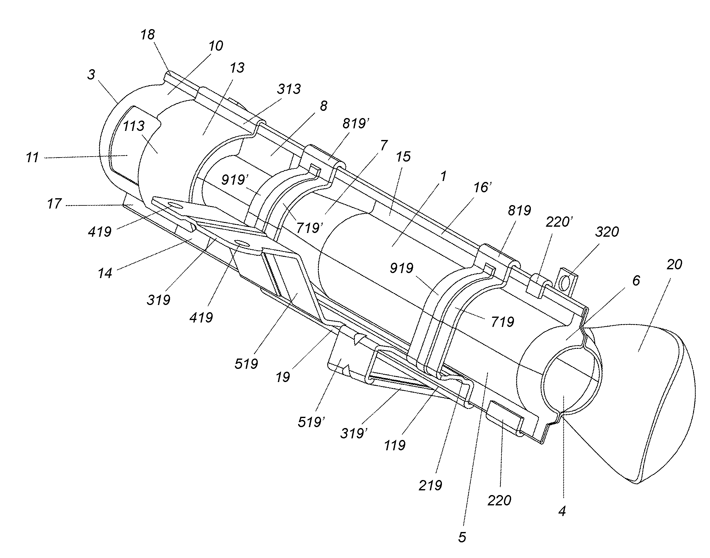
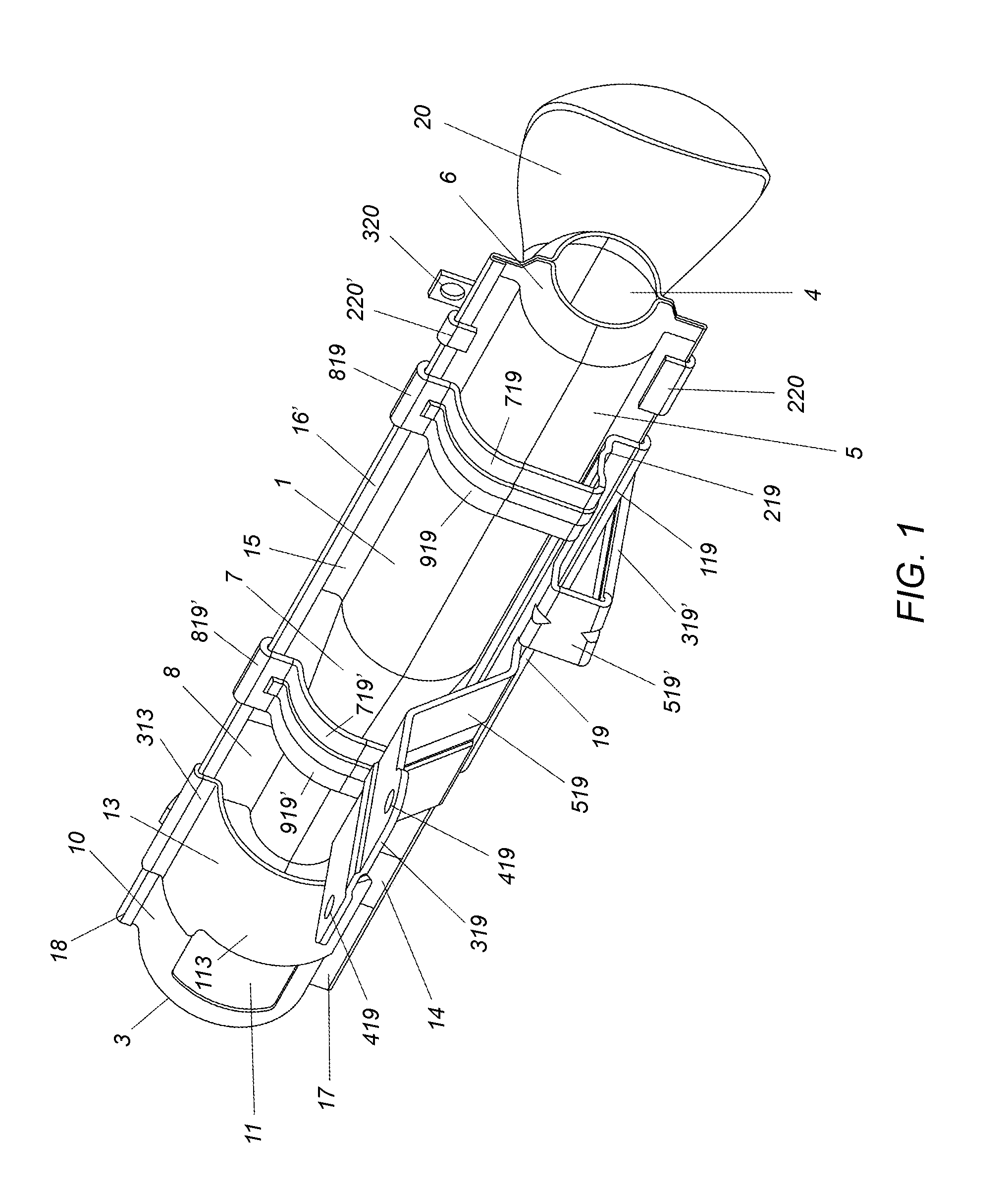
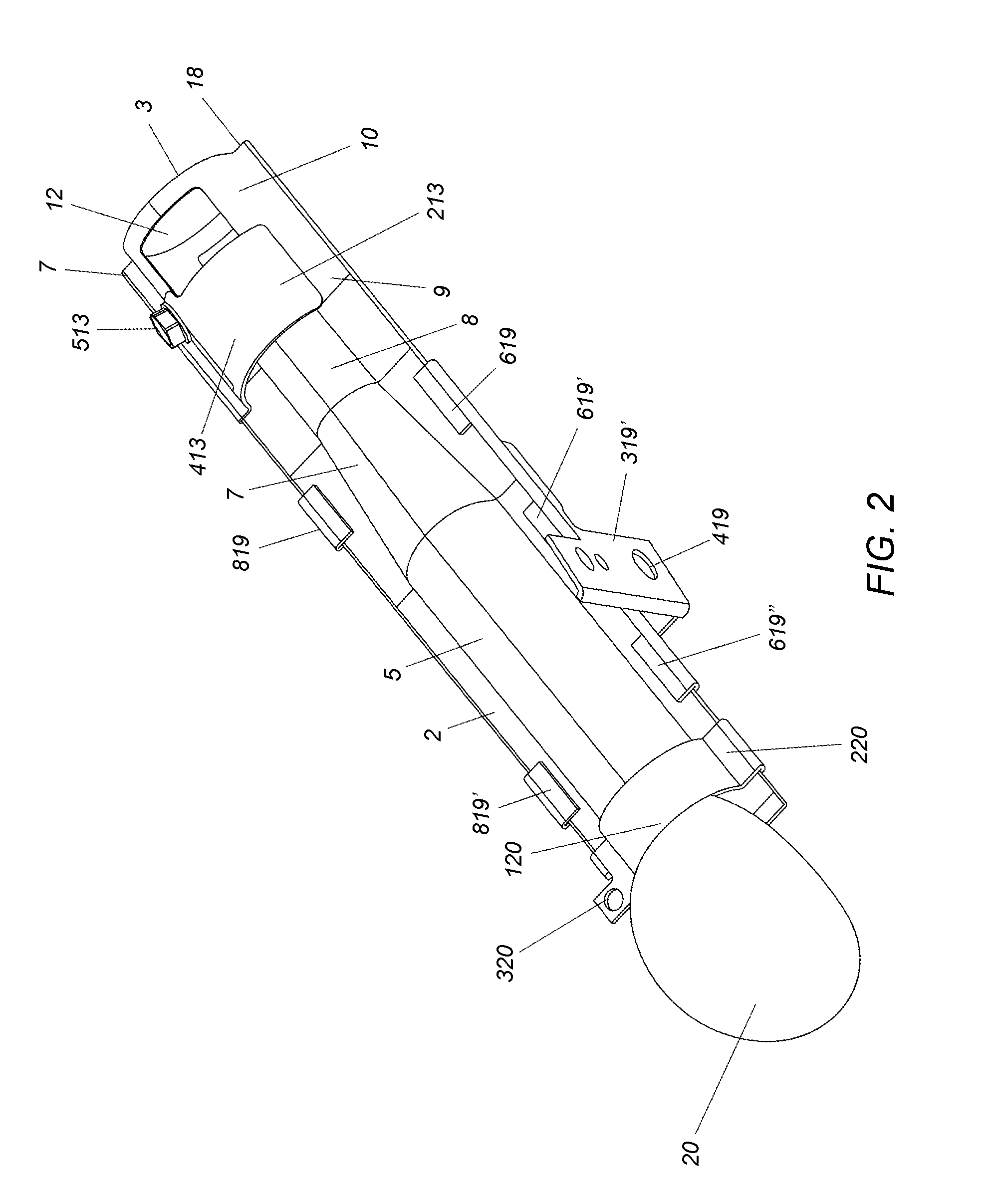
[0055]With reference to FIGS. 1 to 4, an embodiment of the burner according to the present invention comprises a pair of half shells 1, 2 that forms, in the coupled condition, a tubular body having a proximal inlet end 3 for the gas / air mixture and a distal outlet end 4 for said mixture. By way of example the tubular body can be divided into five regions with reference to its cross-section. Starting from the gas / air mixture outlet end 4, there is provided a short junction portion 6 which widens toward a uniform section region 5, then a region 7 where the section tapers toward the inlet end to take a uniform value in the portion denoted by reference number 8. Then the section widens in portion 9 to return again to a uniform section in the final portion 10 near the inlet end 3. The uniform section portion 10 has a pair of opposite circumferential apertures 11 and 12 on the first half shell 1 and on the second half shell 2 respectively in a substantially median position of the portion ...


PUM

PropertyMeasurementUnit
Lengthaaaaaaaaaa
Sizeaaaaaaaaaa
Ratioaaaaaaaaaa

Abstract

A burner for dryers that includes a tubular element having at least a funnel-shaped region tapering toward an inlet end for fuel gas and combustion air to form a gas/air mixing venturi tube, and an opposite having an outlet nozzle for said mixture. According to the invention, the burner body is made of two half shells tightly joined together along corresponding mutually coupling longitudinal flanges, which, once coupled together, form two opposite perimetrical longitudinal edges The burner body has a substantially rectangular plan shape with two longitudinal edges that are parallel substantially for the entire length of the burner body. The invention relates also to a process for manufacturing said burner.

Description

FIELD OF THE INVENTION[0001]The invention relates to a burner that includes a tubular element having at least a funnel-shaped region tapering toward an inlet end for the fuel gas and combustion air to form a gas / air mixing venturi tube, an opposite end having an outlet nozzle for said mixture.BACKGROUND OF THE INVENTION[0002]This type of burners are known and widely used, particularly in the field of dryers. The operational principle is that of induction burners, wherein combustion air under atmospheric pressure is drawn within the burner by the provision of a venturi tube that is a section tapering in the flow direction of the supplying gas, thus leading to an increase in the velocity thereof and also leading to a consequent drop in pressure, which causes air to be drawn in. The amount of drawn air is a function of the section of the air inlet nozzle, which is generally made variable by means of a sleeve that can be locked between a position, in which the nozzle is completely open ...

Claims


Application Information

Patent Timeline
IPC IPC(8): F26B25/06F23D14/46F23D14/62F23D14/12B21D53/00F16M13/02F16M13/00
CPCF23D14/08F23D14/46F23D14/70Y10T29/49348F23D2213/00F23D2900/11401F23D21/005F23D91/02
Inventor OFFREDI, GIORGIO
Owner CASTFUTURA
Why Eureka
Try Eureka