

Reticle cleaning method for a lithography tool and a reticle cleaning system thereof
- Summary
- Abstract
- Description
- Claims
- Application Information
AI Technical Summary
Benefits of technology
Problems solved by technology
Method used
Image

Examples
first embodiment
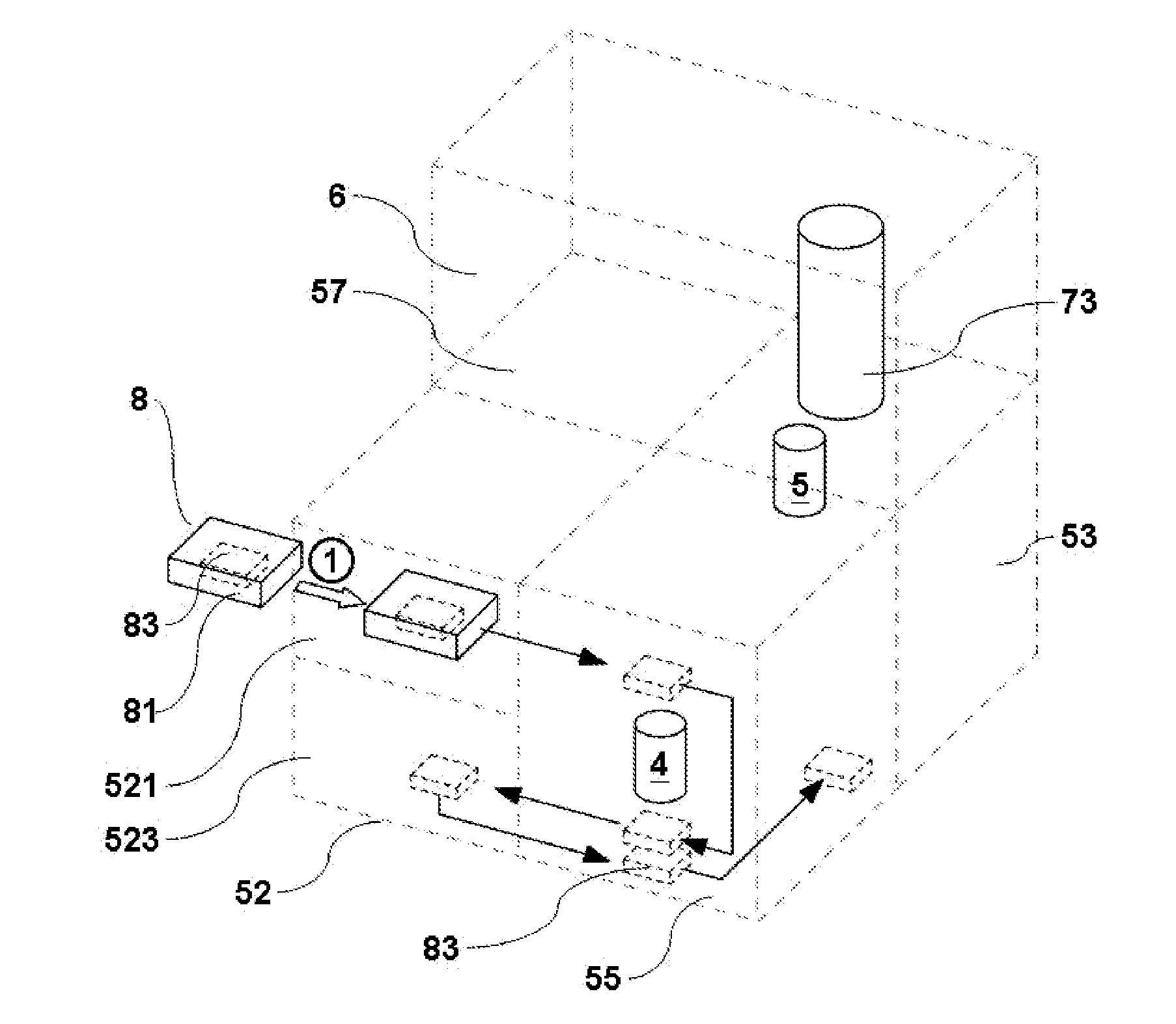
[0025]In the present invention, when the inner box 83 is transported to the lower chamber 523, the inner box 83 is placed on the base 525 of the lower chamber 523 for the gas valves 833 and 835 on the base 525 to correspond with and contact the two gas valves (not shown in Figure) on the inner box 83, as shown in FIG. 4; then, the controller closes the inner side door of the lower chamber 523, commands the vacuum exhausting valve 5251 on the base 525 to perform vacuum exhausting, and then shuts off the vacuum exhausting valve 5251 when the degree of vacuum in the lower chamber 523 reaches 10−1 torr to maintain the degree of vacuum in the lower chamber 523 at 10−1 torr. And the controller then commands the gas valve 833 to fill the inner box 83 with an inert gas (N2 or He for example) for a predetermined quantity and a predetermined gas filling time period; the other gas valve 835 on the base 525 then exhausts the inert gas in the inner box 83 for the inert gas to form gas flow field...
second embodiment
[0026]In addition, in the present invention, when the inner box 83 is transported to the lower chamber 523, the inner box 83 is placed on the base 525 of the lower chamber 523 for the gas valves 833 and 835 on the base 525 to correspond with and contact the two gas valves (not shown in Figure) on the inner box 83, as shown in FIG. 4; then, the controller closes the inner side door of the lower chamber 523, commands the vacuum exhausting valve 5251 on the base 525 to perform vacuum exhausting, and then shuts off the vacuum exhausting valve 5251 when the degree of vacuum in the lower chamber 523 reaches 10−1 torr to maintain the degree of vacuum in the lower chamber 523 at 10−1 torr. And the controller then commands the gas valve 833 to fill the inner box 83 with an ionized inert gas (ionized nitrogen gas produced by passing nitrogen gas through ion-generating apparatus for example) for a predetermined quantity and a predetermined gas filling time period; the other gas valve 835 on th...
PUM
 Abstract
Description
Claims
Application Information