Gas tank

a gas tank and gas pressure technology, applied in the field of gas tanks, can solve the problems of unlikely increase in gas pressure and unlikely increase in temperature of gas filled in the tank main body, and achieve the effect of suppressing the increase of gas pressur

Active Publication Date: 2011-07-28
HONDA MOTOR CO LTD
View PDF5 Cites 40 Cited by
  • Summary
  • Abstract
  • Description
  • Claims
  • Application Information

AI Technical Summary

Benefits of technology

[0044]According to such a gas tank, because the pressure-reduction device is arranged at the right or left of the tank main body in the vehicle-width direction, so that when a vehicle is compressed in the vehicle-length direction by a collision, etc., the pressure-reduction device can be protected and the gas tank which suppresses increasing of a gas pressure can be maintained.

Problems solved by technology

Hence, the temperature of gas filled in the tank main body is unlikely to increase, and thus pressure thereof is unlikely to increase.

Method used


Image

  • Gas tank
  • Gas tank
  • Gas tank

Examples


first embodiment

[0061]A first embodiment of the present invention will be explained with reference to FIGS. 1 to 6.

[0062]>

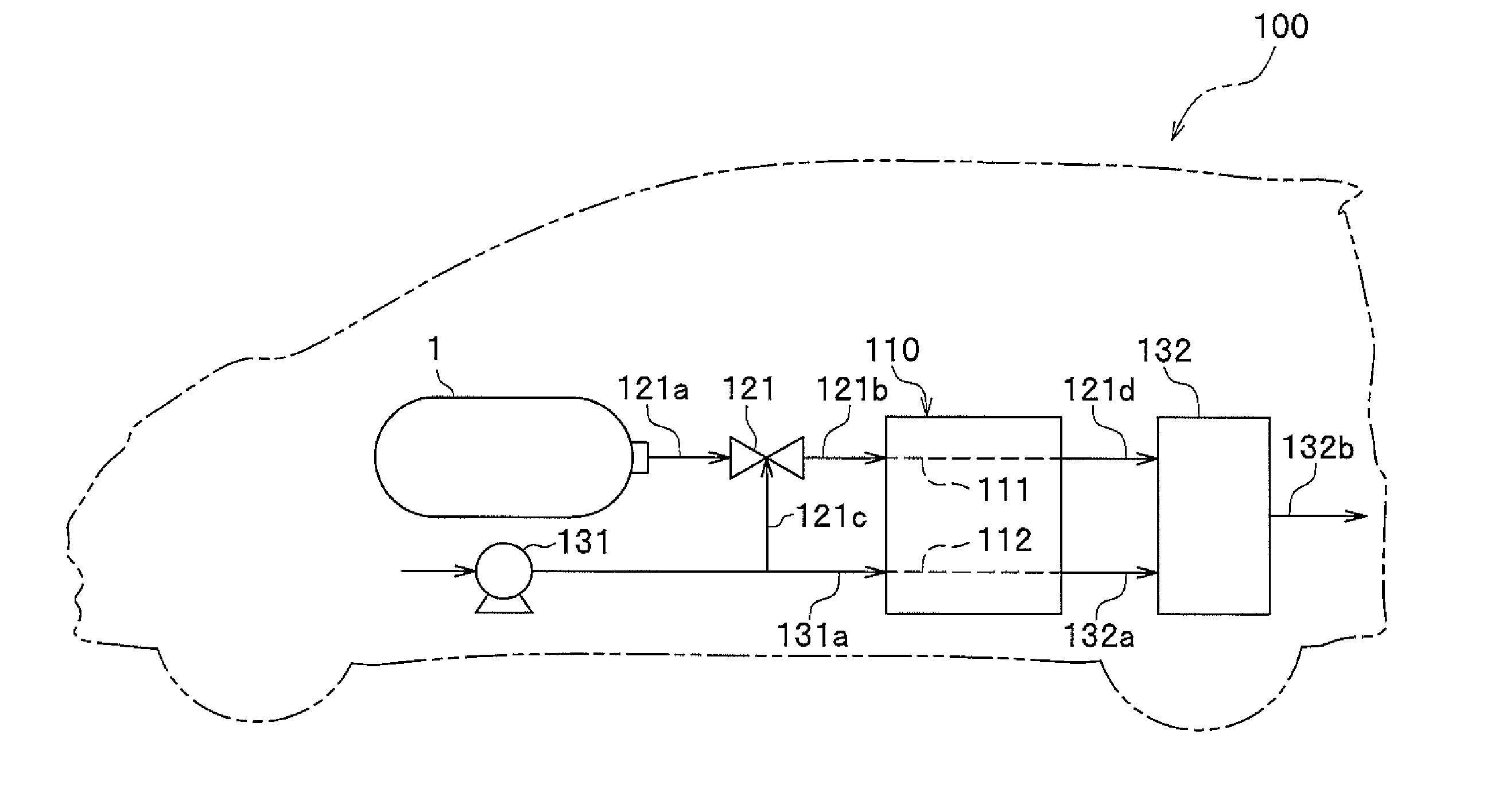
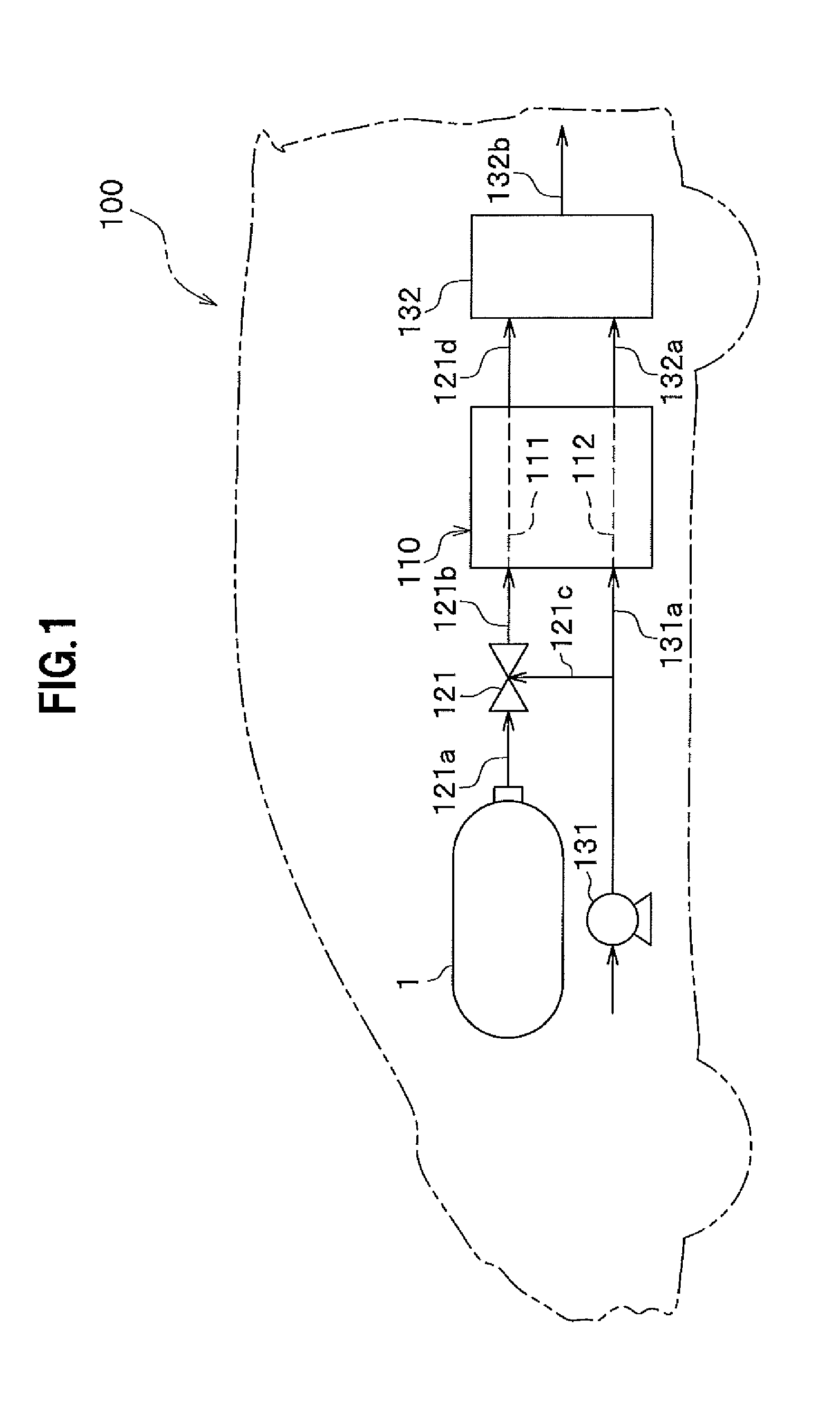
[0063]A fuel cell vehicle 100 (hereinafter, referred to as a travelling object) of this embodiment includes a fuel cell stack 110 (a fuel cell), a hydrogen tank 1 (a gas tank), a pressure-reduction valve 121, a compressor 131, and a dilution unit 132.

[0064]More specifically, the fuel cell vehicle 100 may be, for example, a four-wheel vehicle, a three-wheel cycle, a two-wheel vehicle, a unicycle, or a train.

[0065]The fuel cell stack 110 is a solid-polymer type fuel cell (Polymer Electrolyte Fuel Cell: PEFC), and has a plurality of stacked cells each including an MEA (Membrane Electrode Assembly) sandwiched between separators (not shown). The MEA has an electrolyte membrane (solid-polymer membrane), and a cathode and an anode sandwiching the MEA. Each separator is provided with an anode path 111 (a fuel gas path) and a cathode path 112 (an oxidant gas path) which are grooves or th...

second embodiment

[0113]Next, a second embodiment of the present invention will be explained with reference to FIG. 7. The only differences from the first embodiment will be given.

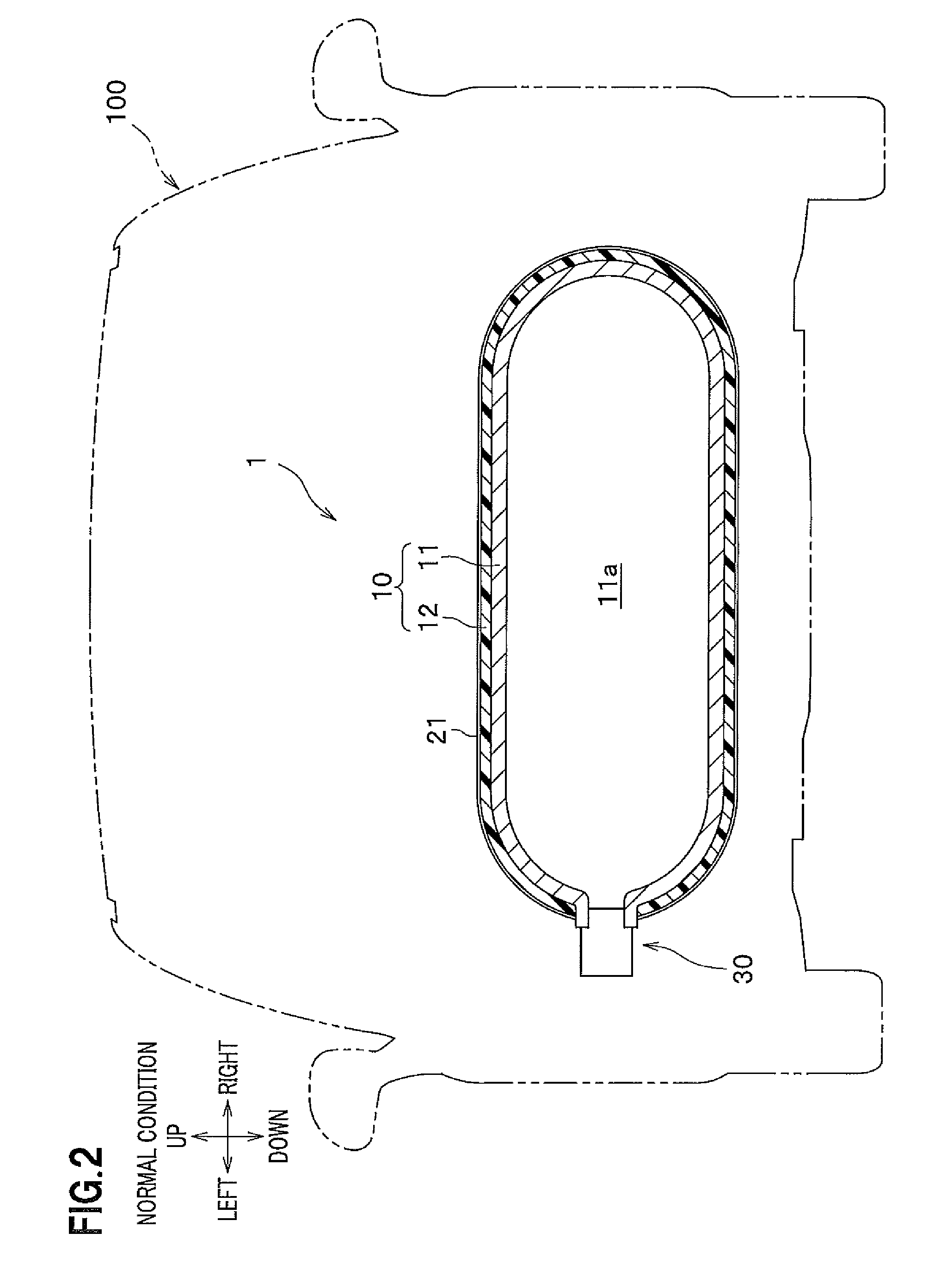
[0114]A hydrogen tank 2 of the second embodiment has, instead of the thermofoamable heat-insulating layer 21, a heat-insulating member 22 (a cover) which is fixed on the external surface 13 of the tank main body 10, and which initially has heat-insulating properties so as to serve a heat-insulating layer as it is. That is, it is unnecessary to apply a thermofoamable heat-insulating paint in order to form the thermofoamable heat-insulating layer 21, thus the hydrogen tank 2 can be simplified. Also, because the heat-insulating member 22 has a predetermined thickness, the hydrogen tank 2 hardly be deformed.

[0115]The heat-insulating member 22 comprises two vertically separated pieces, i.e., an upper half and a lower half, and is bonded, and fixed by using a bond or fastened and fixed by using a bolt, etc. . . . Also, the heat-i...

third embodiment

[0116]Next, a third embodiment of the present invention will be explained with reference to FIGS. 8 to 10. The only differences from the first embodiment will be given.

[0117]A hydrogen tank 3 of the third embodiment has, in addition to the configuration of the hydrogen tank 1 of the first embodiment, a bar-shaped heat pipe 51 (transferring component) arranged in the tank room 11a.

[0118]The left end of the heat pipe 51 is screwed to and fixed to the valve body 31 (see FIG. 9). That is, the heat pipe 51 is thermally coupled to the relief valve 30.

[0119]The heat pipe 51 extends from the relief valve 30 provided at the left end of the tank main body 10 toward the right end of the tank main body 10 in the tank room 11a (see FIG. 10). Also, a heat-insulating member 52 is provided on the surface of the heat pipe 51 other than the left end and the right end.

[0120]Accordingly, when heat is input from the right side of the hydrogen tank 3 into the tank room 11a, the heat is detected at the r...


PUM


Abstract

There is provided a gas tank that suppresses an increase in pressure of a gas filled therein. A hydrogen tank comprises a tank main body filled with hydrogen, a thermofoamable heat-insulating layer provided on the external surface of the tank main body, a relief valve which is provided at the left end of the tank main body and which reduces the pressure in the tank main body by releasing the hydrogen in the tank main body, and a liner which extends from the relief valve toward the right end and which detects an increase in temperature. The relief valve is thermally connected to the liner, and is actuated based on heat transferred from the liner in order to release the hydrogen in the tank main body, thereby reducing the pressure in the tank main body.

Description

CROSS-REFERENCE TO RELATED APPLICATION[0001]The present application claims benefit of priority under 35 USC 119 to Japanese Patent Application No. 2010-013440 filed on Jan. 25, 2010 the entire contents of which are hereby incorporated by reference.FIELD OF THE INVENTION[0002]The present invention relates to a gas tank.DESCRIPTION OF THE RELATED ART[0003]Recently, development of a fuel cell vehicle which is equipped with a fuel cell and which runs by its electrical power is progressed. Such a fuel cell vehicle is also equipped with, in addition to the fuel cell, a hydrogen tank (gas tank) that supplies hydrogen (a fuel gas) to the fuel cell, a compressor that supplies air, a coolant pump that circulates a coolant so as to flow through the fuel cell, a PDU (Power Drive Unit) that converts DC power to AC power, a motor for travelling, and a drive train that transmits the driving force generated by the motor to driving wheels.[0004]External devices including the compressor, the coolant ...

Claims


Application Information

Patent Timeline
Patent Type & Authority Applications(United States)
IPC IPC(8): B65D81/38
CPCB60K15/03006Y10T137/1963
Inventor HANDA, KIYOSHI
Owner HONDA MOTOR CO LTD
Why Eureka
Try Eureka