Aircraft having a lambda-box wing configuration

a technology of lambda box and wing arrangement, which is applied in the direction of fuselage, airflow influencer, transportation and packaging, etc., can solve the problems of reducing the effectiveness of the wing to generate lift, increasing the structural wing and aircraft weight, and reducing the effect of compressible drag

Active Publication Date: 2011-07-28
AIRBUS OPERATIONS SL
View PDF5 Cites 25 Cited by
  • Summary
  • Abstract
  • Description
  • Claims
  • Application Information

AI Technical Summary

Benefits of technology

[0023]According to the invention, the swept-back airfoils 2 and the swept-forward airfoils 3 have sweep angles such that provide a horizontal separation between said swept-back airfoils 2 and swept-forward airfoils 3, this separation reducing the compressible drag in the aircraft flight at high speeds due to the aerodynamic interaction of the airfoils 2 and 3, which is also advantageous for stability and control in flight.
[0024]Also, the horizontal stagger of the swept-back airfoils 2 and swept-forward airfoils 3 of the aircraft configuration according to the invention provides sufficient longitudinal stability and control to the aircraft without the need of a horizontal stabilizer, resulting in a reduction of the overall wetted area and, therefore, in a lower friction drag.
[0025]Moreover, according to the lambda-box wing configuration aircraft of the invention, the center of lift of the swept-back airfoils 2 is located forward of the center of gravity of the aircraft, the center of lift of the swept-forward airfoils 3 being located behind the center of gravity of the aircraft, this configuration helping to provide static stability to the mentioned aircraft.
[0026]Besides, the aircraft having the wing configuration of the lambda-box type of the invention comprises the propulsion system 5 located on the upper side of the swept-forward airfoils 3, in such a way that the noise radiated downwards by the exhaust gases of the propulsion system 5 intercepts the said swept-forward airfoils 3, which act as noise shields reducing the perceived noise the ground during the aircraft flight.

Problems solved by technology

The kinetic energy absorbed by the wingtip vortices is ultimately extracted from the propulsive system of the aircraft and therefore is a form of drag.
These wingtip vortices also modify the airflow around a wing, compared to a wing of infinite span, reducing the effectiveness of the wing to generate lift, thus requiring a higher angle of attack to compensate, and tilting the total aerodynamic force rearwards.
However, in these long and slender wings the lifting forces create large cantilevered loads and therefore large bending moments, especially at the wing roots, which lead to increased structural wing and aircraft weight.
At these high speeds the airflow is accelerated by the shape of the airfoil which may lead to local flow velocities very close or above the speed of sound, which in turn produces a loss of kinetic energy due to irreversible effects in the compression and expansion of the air.
This has lead to a continuous increase in the diameter of aircraft engines during the past decades, to a point where it is becoming difficult to position the engines in the classical location under the wings.
However, this aircraft configuration, where the rear wing is higher than the forward wing, is prone to the well known problem of deep stall, in which the separated airflow from the fore wing at high angles of attack can blank the aft wing, leading to a stable and difficult to recover aircraft pitch-up attitude and loss of lift.
Additionally, the engines are located in the fuselage, so that in cases where the aircraft is subjected to high accelerations, the inertial loads introduced by the engines will have to be transmitted by the fuselage to the wings, leading to increased weight.
However, this aircraft configuration, where the rear wing is higher than the forward wing, is also prone to the well known problem of deep stall.
Additionally, the fact that the two wings are substantially parallel may lead to an increased compressible drag in the flight at high speeds due to the aerodynamic interaction of the wings, which forms a flow channel between them.

Method used


Image

  • Aircraft having a lambda-box wing configuration
  • Aircraft having a lambda-box wing configuration
  • Aircraft having a lambda-box wing configuration

Examples


Embodiment Construction

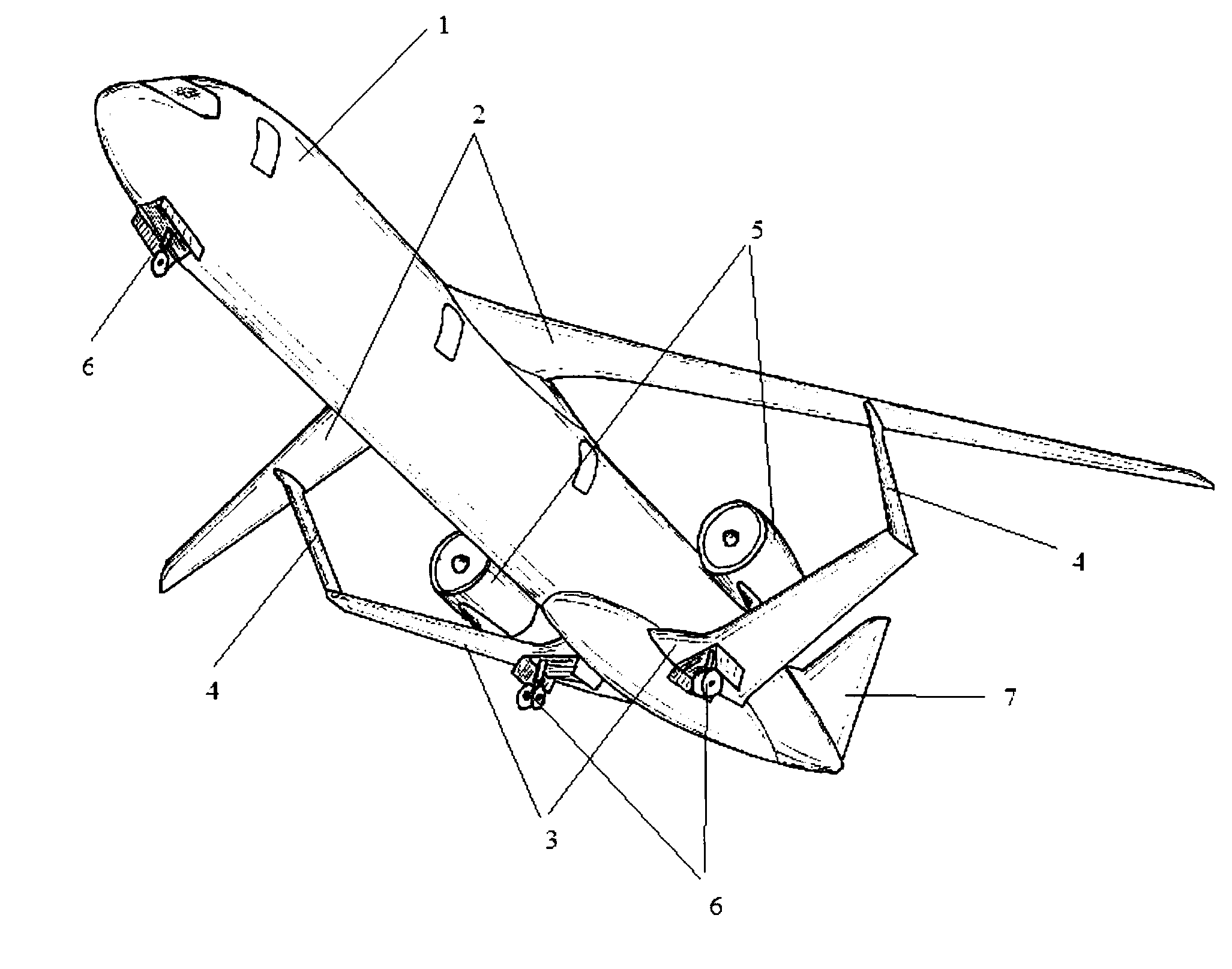
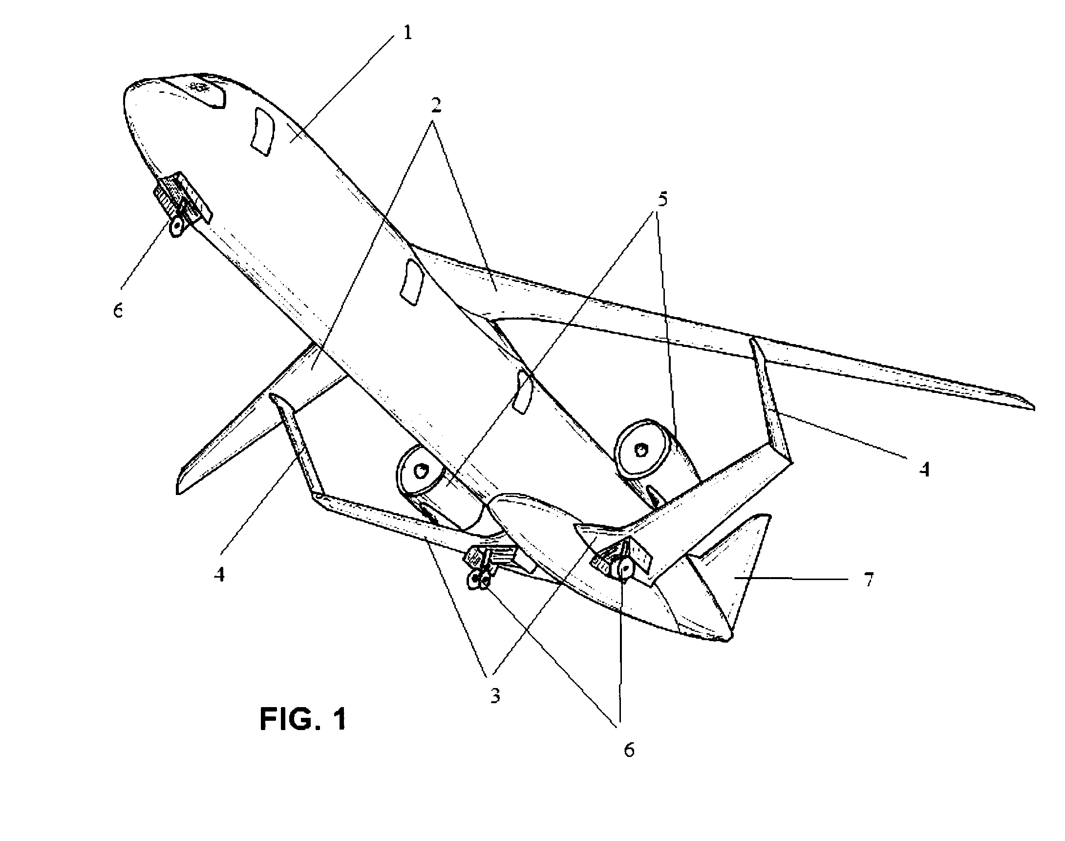
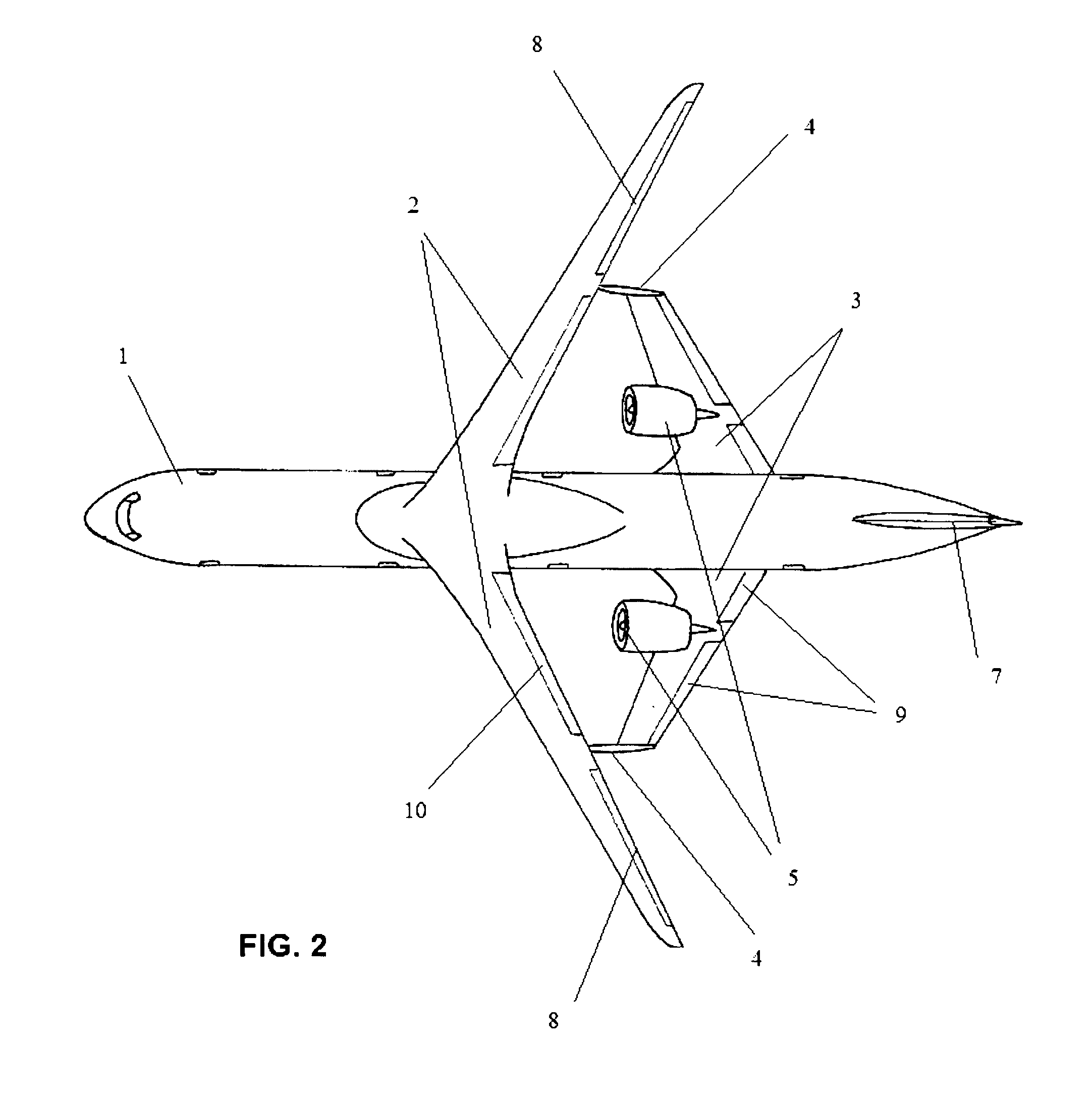
[0034]According to a first aspect, the invention relates to an aircraft comprising: a fuselage 1; a first pair of swept-back airfoils 2, connected to the top forward portion of the fuselage 1; a second pair of swept-forward airfoils 3, connected to the lower rear portion of the fuselage 1; a third pair of substantially vertical airfoils 4, connecting the outermost tip of the swept-forward airfoils 3 to an intermediate point of the span of the swept-back pair of airfoils 2; a propulsion system 5 connected to the pair of swept-forward airfoils 3; a landing gear system 6; at least one substantially vertical airfoil 7 connected to the aft portion of the fuselage 1, which provides directional stability and control to the aircraft.

[0035]The tips of the swept-forward airfoils 3 are connected to the lower side of the swept-back airfoils 2 at an intermediate point of the span of the said swept-back airfoils 2, by means of substantially vertical airfoils 4, acting as an structural joint of th...


PUM


Abstract

Aircraft having a lambda-box wing configuration, comprising a fuselage (1), a propulsion system (5), a first pair of swept-back airfoils (2), connected to the top forward portion of the fuselage (1), a second pair of swept-forward airfoils (3), connected to the lower rear portion of the fuselage (1) at a point of the said fuselage (1) aft of the connection of the swept-back airfoils (2), and a third pair of substantially vertical airfoils (4), the tips of the swept-forward airfoils (3) being connected to the lower side of the swept-back airfoils (2) at an intermediate point of the span of the said swept-back airfoils (2), by means of the substantially vertical airfoils (4), the swept-back airfoils (2) having a higher aspect ratio than that of the swept-forward airfoils (3), which makes the swept-back airfoils (2) have a reduced induced drag without penalizing their weight.

Description

FIELD OF THE INVENTION[0001]The present invention relates to an aircraft having a wing arrangement defining a box or closed frame which reduces the lift-induced drag and which provides an improved structural efficiency of the aircraft as well as a reduction of the perceived engine noise in the ground.BACKGROUND[0002]Economic efficiency is an important consideration in the art of aircraft design. In recent times the environmental impact of the aircraft has also become an important factor included in the design process. In general it can be asserted that both economic and environmental efficiency are improved when the aircraft has a low fuel consumption. The main contributing factors to reduce the fuel consumption of an aircraft are: lower aerodynamic drag, lower structural weight and higher propulsive efficiency.[0003]The aerodynamic drag of an aircraft can be interpreted as the energy per unit length that the aircraft transfers to the air in which it moves and is, in fact, the force...

Claims


Application Information

Patent Timeline
Patent Type & Authority Applications(United States)
IPC IPC(8): B64C39/08B64C1/40B64C25/02B64C1/24
CPCB64C39/068Y02T50/10
Inventor LLAMAS SANDIN, RAUL CARLOS
Owner AIRBUS OPERATIONS SL
Why Eureka
Try Eureka