
Labeler and a labeling method for labeling plastic bottles in a blow mold, in particular in a rotary blow molder

a technology of labeling method and labeling method, which is applied in the direction of labelling, labelling, ceramic shaping apparatus, etc., can solve the problems of inability to rotate, and inability to meet the requirements of manufacturing efficiency of clocked transfer system, etc., to achieve high process reliability and high throughput of bottles

Inactive Publication Date: 2011-07-28
KRONES AG
View PDF14 Cites 4 Cited by
  • Summary
  • Abstract
  • Description
  • Claims
  • Application Information

AI Technical Summary

Benefits of technology

[0008]It is one aspect of the present disclosure to provide a device and a method for in-mold labeling of plastic bottles with high process reliability and a high throughput of bottles, without the above-mentioned drawbacks.

Problems solved by technology

Transfer star wheels with grippers are, however, technically complicated.
Non-rotating, clocked transfer systems do not achieve the manufacturing efficiency demanded.
In the case of these methods the label is, however, substantially stretched together with the preform and the suitability of these methods for lettered labels is therefore very limited.
This method is, however, not suitable for use with preforms prefabricated by injection molding.
This solution, however, limits the design flexibility as regards mold construction and bottle design, it causes problems when the carrier strips are being exchanged, and it is inflexible and technically complicated, since separate supply units are required for the individual blow molds.
The labeling of bottles with the aid of print heads integrated in the blow molds is described e.g. in DE 1479322 A1, U.S. Pat. No. 2,601,700 A or U.S. Pat. No. 3,438,085 A. However, this solution is not suitable for all kinds of bottle designs either.
It is also disadvantageous insofar as at least one print head is required for each blow mold, printing qualities and / or printing formats are restricted, and the dyes must be handled at the blow molder.

Method used


Image

  • Labeler and a labeling method for labeling plastic bottles in a blow mold, in particular in a rotary blow molder
  • Labeler and a labeling method for labeling plastic bottles in a blow mold, in particular in a rotary blow molder
  • Labeler and a labeling method for labeling plastic bottles in a blow mold, in particular in a rotary blow molder

Examples


first embodiment

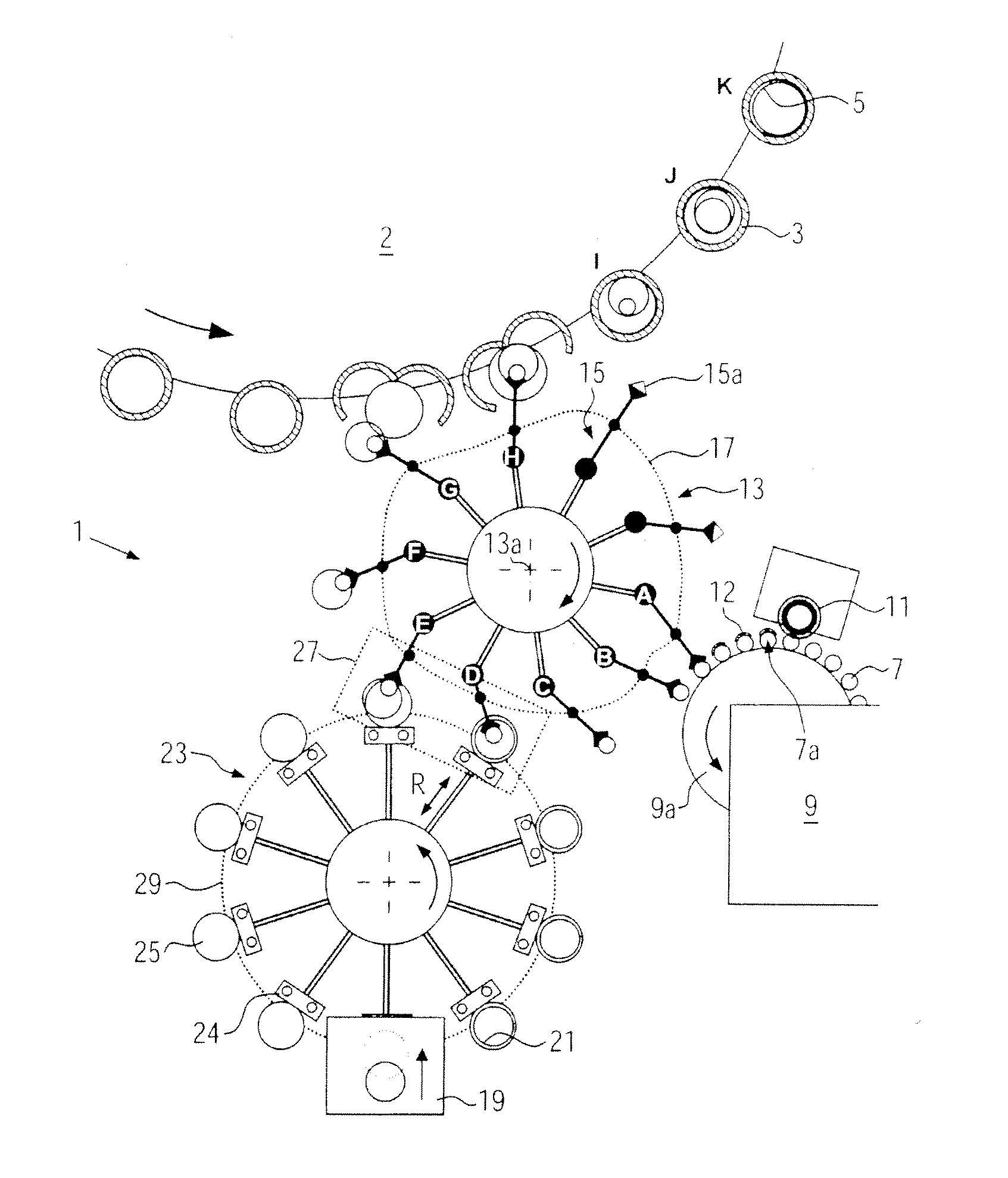
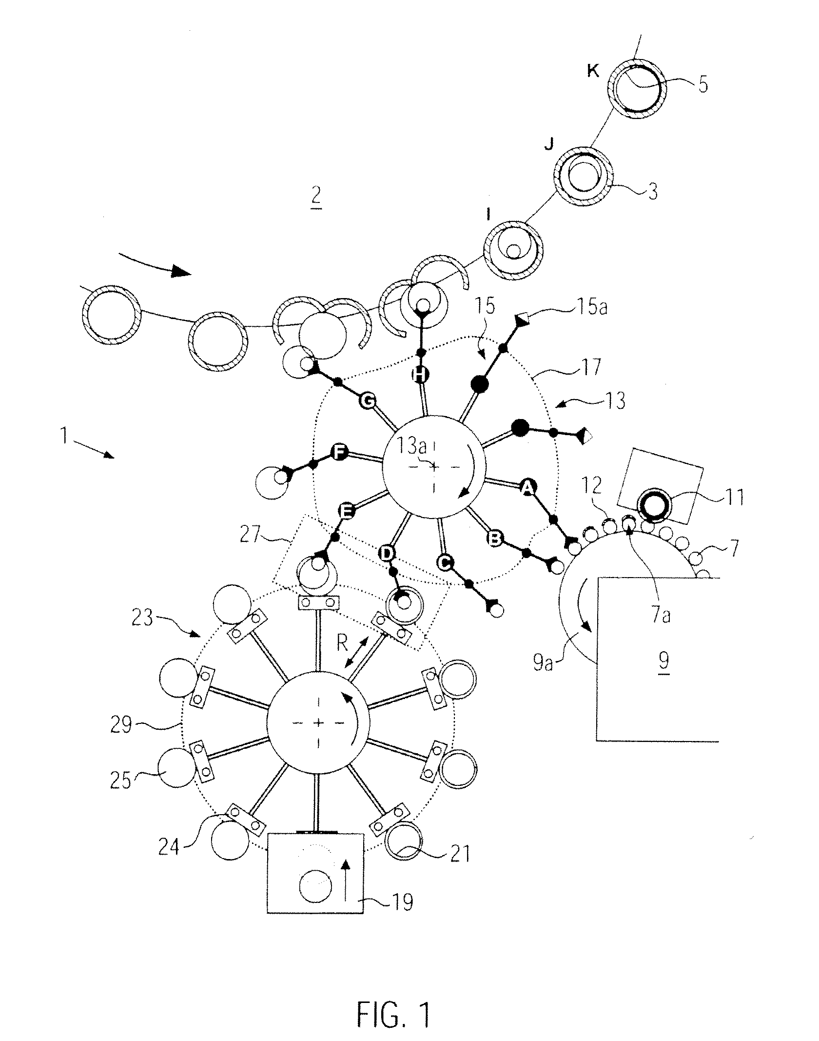
[0032]As can be seen from FIG. 1, the labeler 1 comprises a blow wheel 2 with a plurality of blown molds 3 for producing labeled bottles 5 or other plastic containers from preforms 7. The latter are heated in an oven 9 in the manner known, whereupon a circumferential subarea 7a of said preforms 7 has tangentially applied thereto a glue 12 by means of a gluing roller 11 and the preforms 7 are taken over by a transfer star wheel 13, pitch adaptation star wheel. On the circumference of said transfer star wheel 13 there are provided rotatably supported gripping arms 15, which are variable in length and which are equipped with grippers 15a for the preforms 7, as well as a first control cam 17 for controlling the gripping arms 15, in particular for adjusting the radial position and the track speed of the gripping arms 15.

[0033]In addition, there are provided at least one label dispenser 19, such as a sleeving unit for wrap-around labels 21 or label sleeves 21, and a preferably star-shaped...

third embodiment

[0050]FIG. 4 shows, at three successive moments in time T1 to T3, a gripper 15a and a label dispenser 19 of a third embodiment, in which the transfer device 42 for the labels 21 is arranged in a stationary manner on the label dispenser 19 or integrated in a label dispenser 19, e.g. in a sleeving unit. The transfer device 42 comprises e.g. a friction wheel drive for the labels 21. Also in this case, the additional transfer star wheel of the transfer device 23 shown in FIG. 1 can be dispensed with. Instead, the transfer device 42 is arranged below the track of the glue-coated preforms 7 held by the grippers 15a. The transfer device 42 is configured such that it shoots the label 21 upwards at a moment in time T1 at which the preform 7 is located above the label sleeve 21. The moment in time T1 and the speed of the label 21 are coordinated with the movement of the preform 7 (cf. the horizontal arrows) such that the label sleeve 21 will slip over the preform 7 (cf. T2,) and encompass the...

fourth embodiment

[0052]FIG. 5 shows a fourth embodiment in the case of which planar labels 21, instead of label sleeves, are affixed to the preform 7 by means of the transfer device 44. In contrast to the preceding embodiments, the label 21 is here preferably coated with the glue 12 in a certain area or in certain areas thereof. The label 21 is removed from a magazine (not shown) by means of a palette 45 of a conventional glue pallet carousel and transferred to a turning and transfer device 47, e.g. to a conventional cylinder with vacuum grippers or mechanical grippers. The turning and transfer device 47 conducts the labels 21 tangentially along the transfer star wheel 13 and the gripping arms 15 (not shown) press a respective preform 7 against a glue-coated area 21a of the label 21, thus affixing the labels 21 to the preforms 7. If necessary, the strength and the area of the glued joint can be increased still further by means of a contact-pressure device 49, e.g. by blowing air onto the label or by...


PUM

PropertyMeasurementUnit
Angleaaaaaaaaaa
Adhesion strengthaaaaaaaaaa
Areaaaaaaaaaaa

Abstract

A labeler for in-mold labeling of plastic bottles as well as to a labeling method for use of the labeler, including that a transfer star wheel and a transfer device of the labeler move the preforms and the labels in a transfer region towards one another in such a way that a respective label is only affixed to a circumferential subarea of a perform. In this manner, the label can be inserted in the blow mold in a particularly fast and reliable manner and excessive stretching of the label during blow molding can be avoided.

Description

CROSS-REFERENCE TO RELATED APPLICATION[0001]The present application claims the benefit of priority of German Application No. 102010001184.3, filed Jan. 25, 2010. The entire text of the priority application is incorporated herein by reference in its entirety.FIELD OF THE DISCLOSURE[0002]The disclosure relates to a labeler for in-mold labeling of plastic bottles as well as to a labeling method for use of the labeler.BACKGROUND[0003]As is generally known, plastic bottles can be already be labeled in the course of the production process through so-called in-mold labeling (IML) by introducing the labels in the blow mold before blow molding is executed. To this end, the label is positioned by means of grippers on the inner wall of the opened blow mold, as described in U.S. Pat. No. 6,649,119,B2, U.S. Pat. No. 5,266,149 A and WO 00 785 26 A1 for rotary blow molders. Transfer star wheels with grippers are, however, technically complicated. Non-rotating, clocked transfer systems do not achie...

Claims


Application Information

Patent Timeline
IPC IPC(8): B29C49/24
CPCB29B2911/14313B29C49/02B29C49/24B29C49/2408B29C49/36B65C3/00B29C2049/2412B29C2049/2422B29C2049/2433B29C2049/2443B29C2049/2449B29C2049/021B29C2949/3092B29C2949/08
Inventor HAUSLADEN, WOLFGANGPOPP, CHRISTIANBRITTEN, WERNER
Owner KRONES AG
Learn More