
Method And Apparatus For Detection of A Liquid Under A Surface

a technology of liquid detection and surface, applied in the field of methods and apparatus for the detection of liquids under surfaces, can solve the problems of not being used in the field, no effective technique for remotely sensing the location and extent of spillage under ice, and oil trapped beneath i

Inactive Publication Date: 2011-07-28
EXXONMOBIL UPSTREAM RES CO
View PDF39 Cites 29 Cited by
  • Summary
  • Abstract
  • Description
  • Claims
  • Application Information

AI Technical Summary

Benefits of technology

[0017]In a third embodiment of the present invention an apparatus for detecting a liquid hydrocarbon under a surface is provided. The apparatus comprises a nuclear magnetic resonance (NMR) tool having an antenna for sending and receiving signals mounted to an airborne platform and configured to receive the NMR tool and the antenna, wherein the antenna is a wire loop having a largest dimension of from about five meters to less than about twenty meters. The apparatus may be used in combination with the methods of the present invention.

Problems solved by technology

Oil production or transfer in ice-prone marine or freshwater locations could result in a subsurface release—for example from a well blowout or leaking pipeline—that results in oil trapped beneath ice.
Currently, there is no effective technique to remotely sense the location and extent of a spill under ice.
All of these techniques have shown the capability to detect oil under ice with some success; however, they have not been used in the field.
The methods proposed to date have a limited range of applicability and are susceptible to false positive results.
They also have only a limited ability to “see” or detect oil through a layer of ice and require contact with the ice surface.
The surface access limitation presents both logistic and safety concerns such as breakthrough, and limits the coverage to a small area per day.
However, this technique is limited to the detection of oil at the surface or only a few millimeters below the surface because the opaque nature and heterogeneity of both ice and snow scatter the luminescence to obscure the signal.
Current techniques for detecting oil under ice are not effective or accurate enough to support a proper response in the event of an oil spill.
In addition, these techniques are labor-intensive and dangerous due the surface contact requirement.
Ice characterization technology is similarly limited to ground penetrating radar (GPR), electromagnetic (EM), and satellite detection methods.
While NMR tools have been used for a variety of applications, the technology has not been used to detect oil spilled under a surface such as water, ice, or snow, nor has it been used to characterize ice.

Method used


Image

  • Method And Apparatus For Detection of A Liquid Under A Surface
  • Method And Apparatus For Detection of A Liquid Under A Surface
  • Method And Apparatus For Detection of A Liquid Under A Surface

Examples


Embodiment Construction

[0027]In the following detailed description section, the specific embodiments of the present invention are described in connection with preferred embodiments. However, to the extent that the following description is specific to a particular embodiment or a particular use of the present invention, this is intended to be for exemplary purposes only and simply provides a description of the exemplary embodiments. Accordingly, the invention is not limited to the specific embodiments described below, but rather, it includes all alternatives, modifications, and equivalents falling within the true spirit and scope of the appended claims.

[0028]The term “surface” as used herein refers to a layer of aqueous material that obscures visual detection of substances below the surface. More specifically, the surface may be snow, ice, or a layer of water or any combination thereof, such as, for example, broken up ice floating in water. The term surface does not include non-aqueous surfaces such as ear...


PUM


Abstract

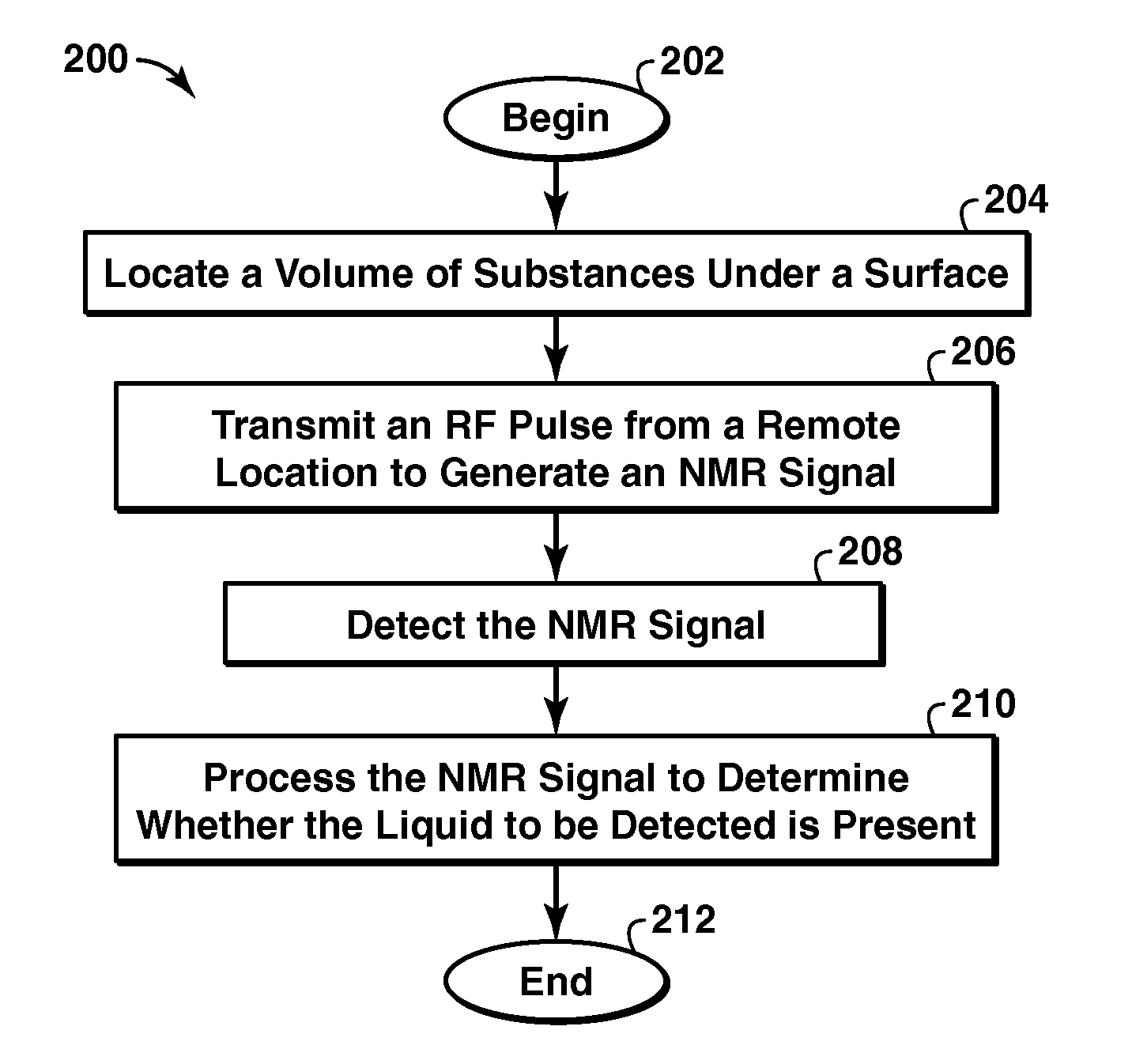
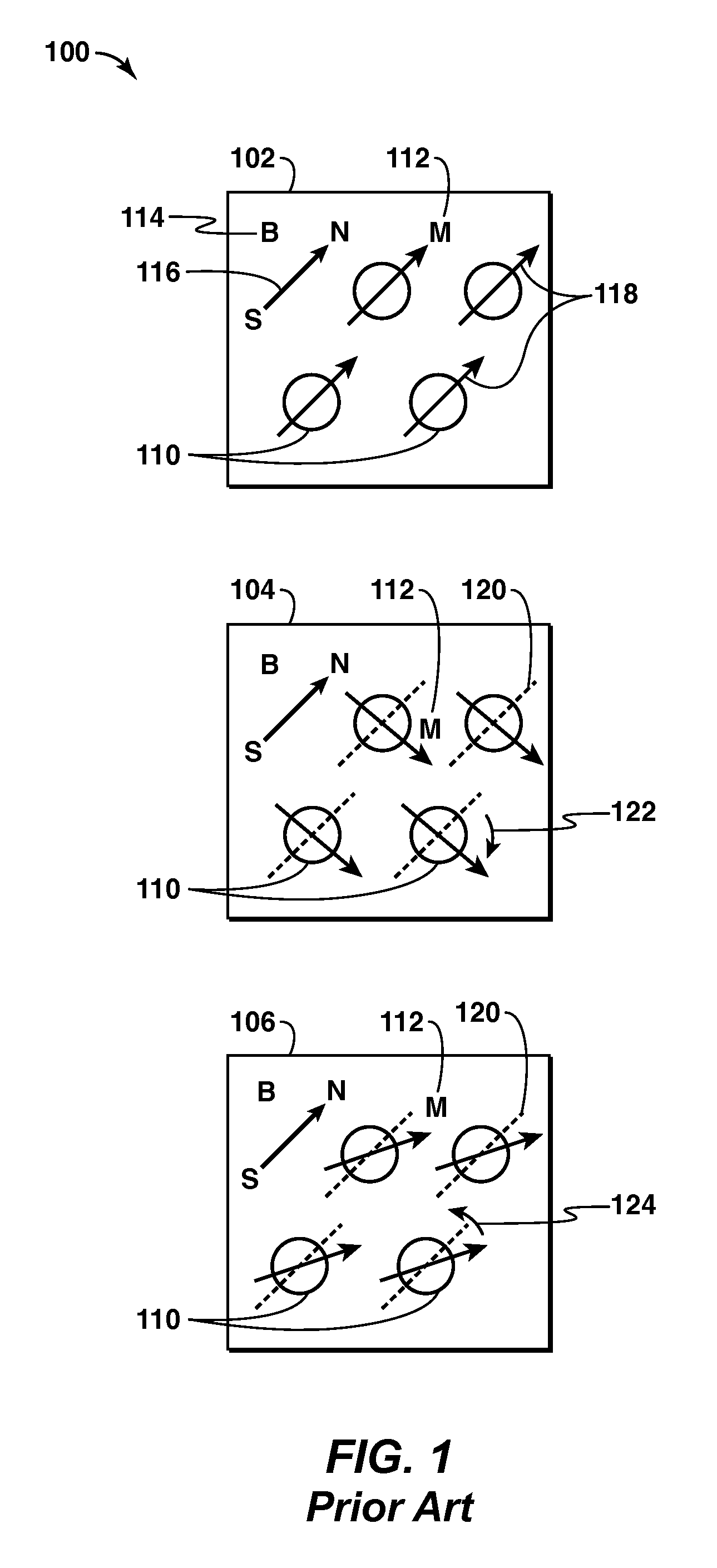
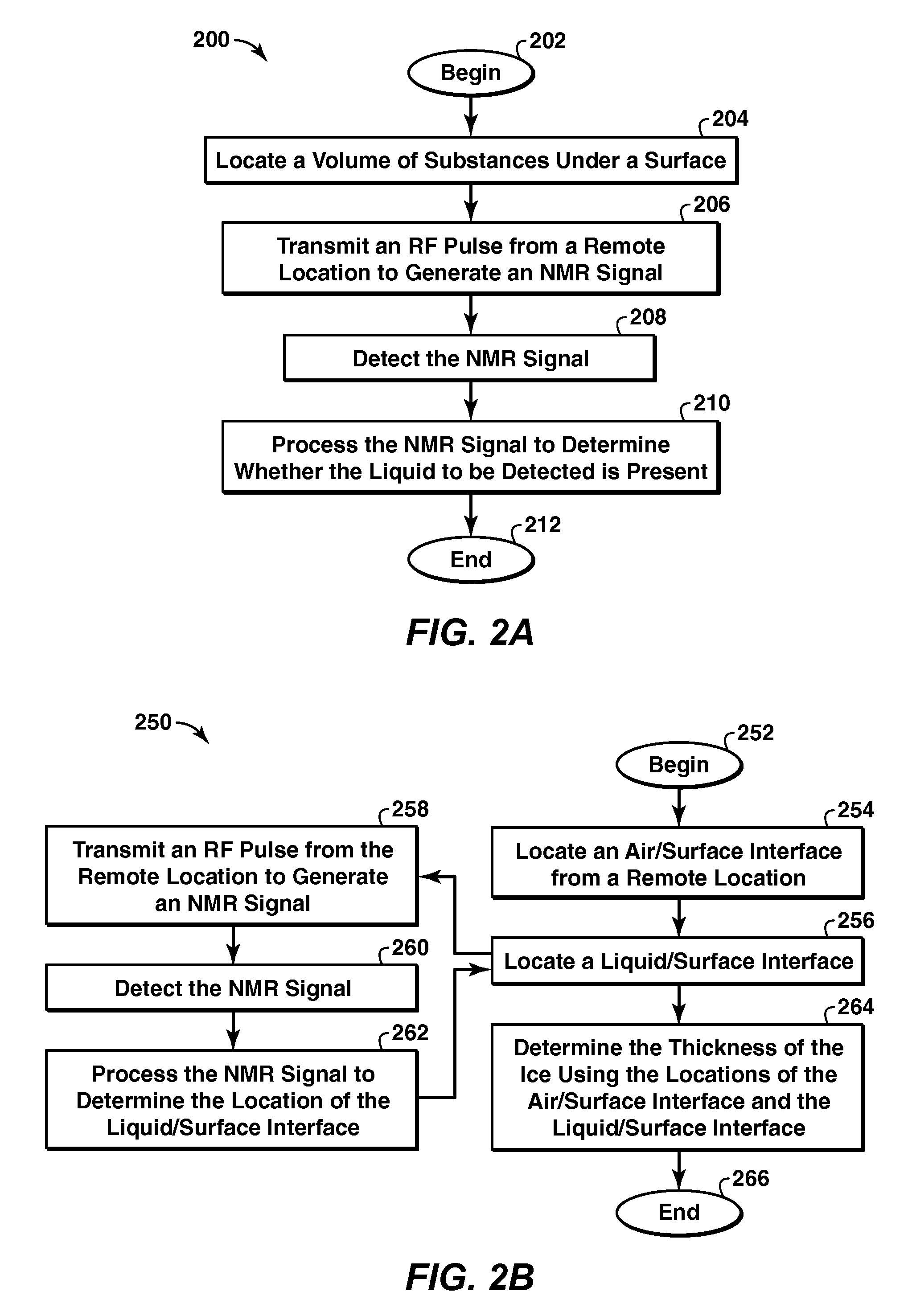
Methods for detecting a liquid under a surface and characterizing Ice are provided The liquid may be a liquid hydrocarbon such as crude oil or fuel oil or mineral oil The surface may be ice, snow, or water, and the method may be practiced in an arctic region to detect oil spills, leaks, or seepages The methods may be used with a range finder to characterize marine ice The methods may include a nuclear magnetic resonance (NMR) tool with antenna to send a radio-frequency (RF) excitation pulse or signal into volume of substances being detected, detect an NMR response signal to determine the presence of the liquid of interest The NMR response may include a relaxation time element and an intensity level and may include a free induction signal (T2*), a spin echo signal (T2), a train of spin echo signals (T2), or a thermal equilibrium signal (T 1).

Description

CROSS REFERENCE TO RELATED APPLICATIONS[0001]This application claims the benefit of U.S. Provisional Application No. 60 / 997,876, filed Oct. 5, 2007.BACKGROUND[0002]This application generally relates to a method and apparatus for the detection of a liquid under a surface. More particularly, a method of remotely detecting oil spilled under a layer of ice, snow, or water is disclosed herein.[0003]This section is intended to introduce various aspects of the art, which may be associated with exemplary embodiments of the present invention. This discussion is believed to assist in providing a framework to facilitate a better understanding of particular aspects of the present invention. Accordingly, it should be understood that this section should be read in this light, and not necessarily as admissions of prior art.[0004]Oil production or transfer in ice-prone marine or freshwater locations could result in a subsurface release—for example from a well blowout or leaking pipeline—that result...

Claims


Application Information

Patent Timeline
Patent Type & Authority Applications(United States)
IPC IPC(8): G01R33/44
CPCG01N24/08G01V3/175G01R33/50G01N24/081Y02A90/30
Inventor SRNKA, LEONARD J.NEDWED, TIMOTHY J.THOMANN, HANSSANDSTROM, ROBERT E.
Owner EXXONMOBIL UPSTREAM RES CO
Learn More