Shaft/Hub Connection and Manually Guided Implement

a technology of shaft and hub, applied in the direction of couplings, rod connections, fastening means, etc., can solve the problems of increasing stress that occurs during dynamic operation simultaneously, and prolonging service life, so as to reduce dynamic stress, reduce dynamic fatigue stress, and ensure the effect of good service li

Inactive Publication Date: 2011-07-28
ANDREAS STIHL AG & CO KG
View PDF11 Cites 7 Cited by
  • Summary
  • Abstract
  • Description
  • Claims
  • Application Information

AI Technical Summary

Benefits of technology

[0018]To reduce the dynamic fatigue stresses, the hub can be extended beyond the conical shaft extension on that side that has the maximum inner diameter, thereby forming an extension. In this connection, the opening of the hub advantageously also extends conically in the region of the hub extension. A conical annular gap thus results between the extension of the hub and the shaft. In the extending region, no forces are introduced into the hub, so that this region serves for reinforcement. Consequently, the dynamic stresses can be reduced. The extension advantageously has an axial length that corresponds to approximately 10% to approximately 50% of the greatest diameter of the shaft extension. The axial length of the extension is advantageously more than 20% of the greatest diameter of the shaft extension.
[0019]The length of the hub, measured in the direction of the axis of rotation, advantageously corresponds to approximately one half to approximately twice the maximum outer diameter of the hub in the region of the stress-relieving or antifatigue means. This enables an adequate strength of the hub.
[0020]In particular when providing an extension on the hub, a reduction of the outer diameter of the hub is provided. The maximum outer diameter of the hub in the region of the stress-relieving or antifatigue means expediently corresponds to less than approximately 190%, and especially less than approximately 175%, of the greatest diameter of the shaft extension. The outer diameter of the hub is reduced in comparison to known hub configurations. Consequently, the dynamic fatigue stresses that occur can be kept low. In this connection, the diameter of the hub in the region of the stress-relieving or antifatigue means, especially in the region of the extension, can decrease. In this connection, for example, a rounded-off or conical course of the outer diameter can be provided. The minimum outer diameter of the hub in the region of the stress-relieving or antifatigue means is advantageously less than approximately 175%, especially less than approximately 150%, of the greatest diameter of the shaft extension. The axial length of the shaft extension is expediently approximately 70% to approximately 150% of the greatest diameter of the shaft extension. To achieve a reliable connection of shaft and hub, the connection can be provided with means for a positive or interlocking securement of the position of rotation of hub and shaft relative to one another. The means for the positive securement can, for example, include an adjusting spring. Other means for the positive securement can also be advantageous.
[0021]The hub is advantageously formed at least partially in a bead of the flywheel. The greatest diameter of the bead is advantageously at least approximately 160% of the greatest diameter of the shaft extension. The axial length of the bead is advantageously approximately 30% of the greatest diameter of the shaft extension. This results in a good strength of the hub during operation, although the hub can have a low weight.

Problems solved by technology

In this connection, however, the stresses that occur during the dynamic operation simultaneously increase.
A massive design of the hub does not necessarily lead to a longer service life.

Method used


Image

  • Shaft/Hub Connection and Manually Guided Implement
  • Shaft/Hub Connection and Manually Guided Implement
  • Shaft/Hub Connection and Manually Guided Implement

Examples


Embodiment Construction

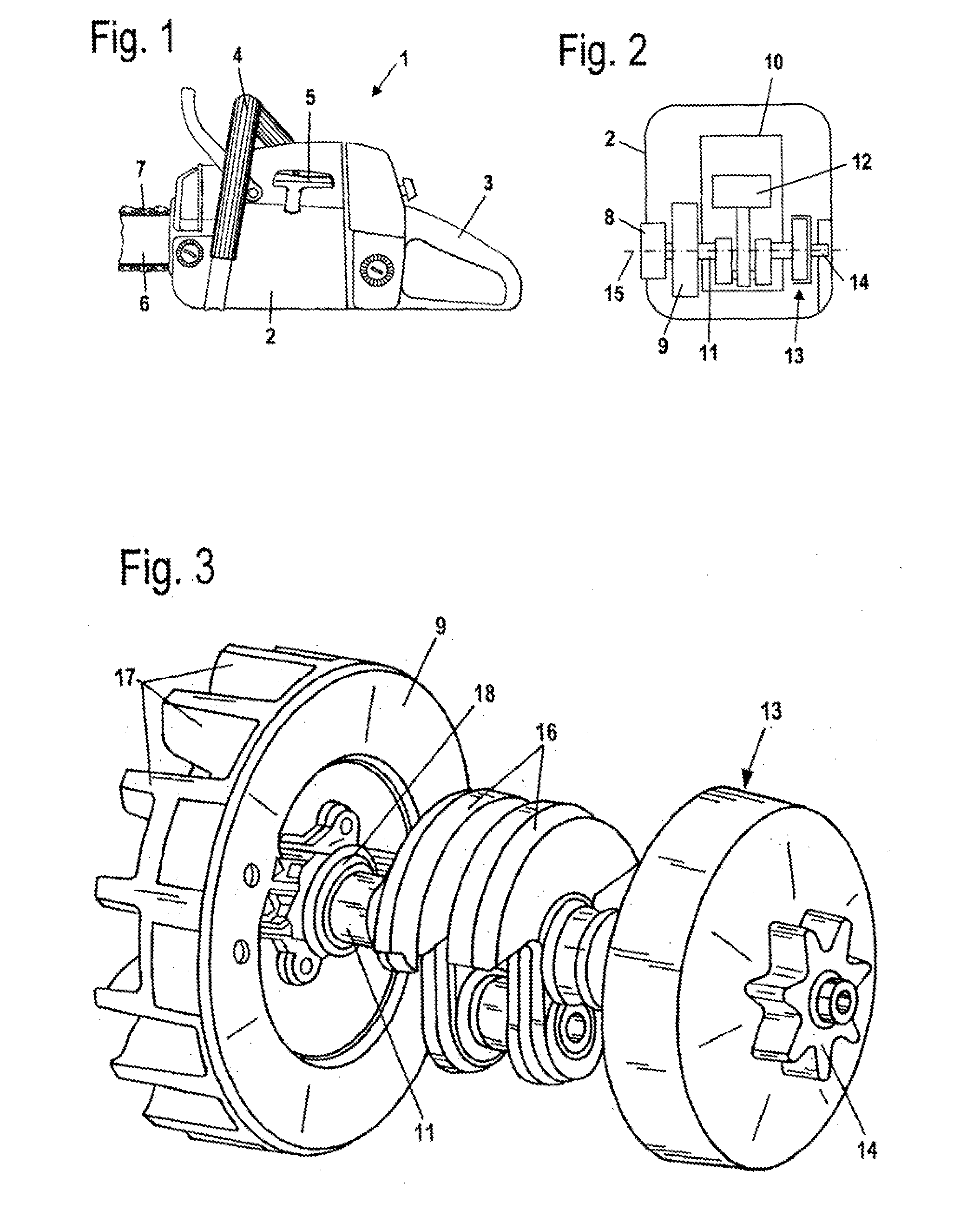
[0023]Referring now to the drawings in detail, the power saw 1, which is schematically shown in FIG. 1, has a housing 2 on which are secured a rear handle 3 and a tubular handle 4 for guiding the power saw 1. Extending from the housing 2 is a starter handle 5 for starting the drive motor of the power saw 1. Disposed on the power saw 1 is a guide bar 6 on which a saw chain 7 is driven in a circulating manner.

[0024]The saw chain 7 is driven by the driving pinion 14, which is shown in FIG. 2. The pinion 14 is connected via a centrifugal clutch 13 with a crankshaft 11 of an internal combustion engine 10 that is disposed in the housing 2. The internal combustion engine 10 is, in particular, a two-cycle engine or a mixture-lubricated four-cycle engine. The crankshaft 11 is driven in a rotating manner about an axis of rotation 15 by a piston 12 of the internal combustion engine 10.

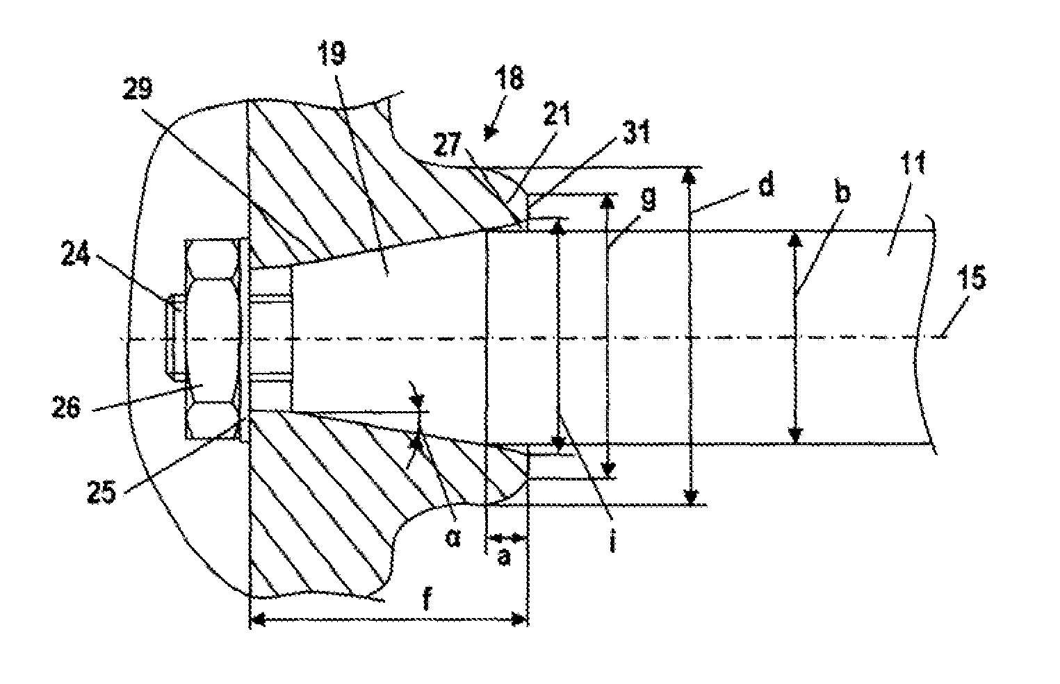
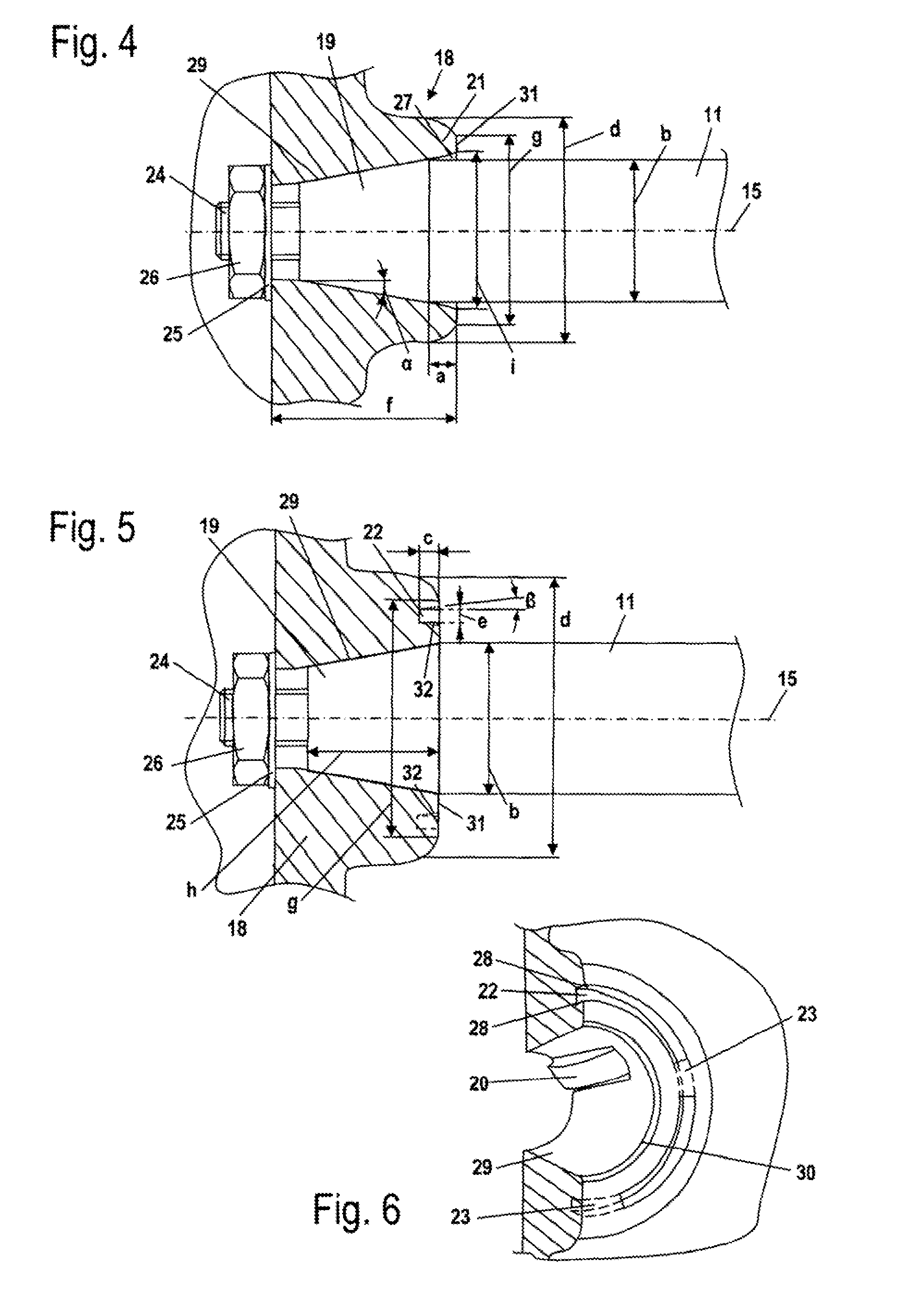
[0025]On that side of the internal combustion engine 10 opposite the driving pinion 14 a flywheel 9 is secured...


PUM


Abstract

A shaft/hub connection between a shaft rotatably driven about an axis of rotation, and a hub disposed on the shaft so as to be non-rotatable relative thereto. The hub has a conical opening and an end face at that end of the hub having the greatest inner diameter. The hub also has at least one relief groove that extends into the hub from the end face thereof. A conical shaft extension on the shaft extends into the conical opening of the hub and is held in the hub via a conical pressure connection.

Description

[0001]The instant application is a Continuation-In-Part application of Ser. No. 12 / 177,397 filed Jul. 22, 2008 and should also be granted the priority date of Jul. 27, 2007 the filing date of the corresponding German patent application DE 10 2007 035 37.7.BACKGROUND OF THE INVENTION[0002]The present invention relates to a shaft / hub connection between a shaft that is rotatably driven about an axis of rotation, and a hub component that is disposed on the shaft so as to be non-rotatable relative thereto.[0003]With manually guided implements, such as power saws, cut-off machines, or the like, it is known to dispose a flywheel on the crankshaft via a conical pressure connection. During operation, high dynamic stresses are superimposed over the static base load of the flywheel hub. This can lead to a shortening of the service life of the flywheel.[0004]It is an object of the present application to provide a shaft / hub connection of the aforementioned general type that has a long service li...

Claims


Application Information

Patent Timeline
Patent Type & Authority Applications(United States)
IPC IPC(8): F16D1/06F16D1/00
CPCF16D1/092Y10T403/70Y10T403/7075
Inventor KEMMLER, RALF-RAINERBOHNAKER, EBERHARD
Owner ANDREAS STIHL AG & CO KG
Why Eureka
Try Eureka