Method of controlling a wind power plant

Active Publication Date: 2011-07-28
VESTAS WIND SYST AS
View PDF15 Cites 21 Cited by
  • Summary
  • Abstract
  • Description
  • Claims
  • Application Information

AI Technical Summary

Benefits of technology

[0008]A general object is to provide enhanced

Problems solved by technology

However, for wind power plants, the unpredictable nature of the wind renders it more difficult to control the power output from these plants at a given time.
However, the usage of diesel generators is a supple

Method used


Image

  • Method of controlling a wind power plant
  • Method of controlling a wind power plant
  • Method of controlling a wind power plant

Examples


Embodiment Construction

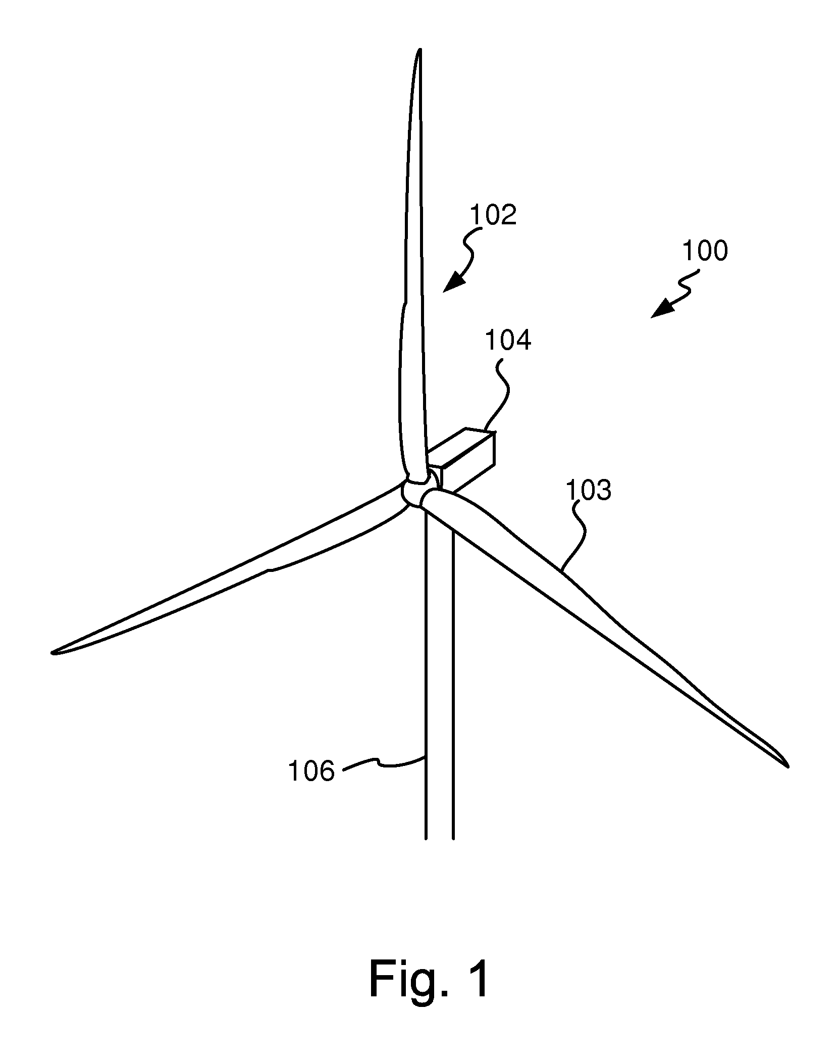
[0082]FIG. 1 is a perspective view of an example of a wind turbine 100. The wind turbine 100 comprises a rotor 102, a nacelle 104 and a tower 106. The rotor 102 usually comprises two or three rotor blades 103. The rotor blades 103 can be manufactured of e.g. glass fiber reinforced plastics or carbon fiber. Usually, the rotor blades 103 can be pitched, i.e. the angle of the rotor blades 103 can be altered in a longitudinal direction of the rotor blades 103 by a pitch mechanism (not shown), for example in case of too high wind speeds.

[0083]None of the components comprised within the nacelle 104 are illustrated in FIG. 1, however, the nacelle 104 can comprise a gearbox for gearing up a rotor speed generated by the rotor 102.

[0084]The wind turbine 100 can either operate at fixed speed or variable speed. If the wind turbine 100 is of a variable speed type, a generator housed within the nacelle 104 is controlled by power electronic equipment.

[0085]The generator can e.g. be an asynchronous...


PUM


Abstract

It is presented a method for controlling the instantaneous power output from a wind power plant. Wind speed and wind directions are determined, wherein an upper limit power output for the specific wind speed and wind direction is determined from a previously measured power output value at the same wind speed and wind direction, and wherein the power output of the wind power plant is controlled based on the determined upper limit power output. A wind power plant is also presented.

Description

TECHNICAL FIELD[0001]The present invention relates to a method of controlling a wind power plant and to a computer program for carrying out said method when running on a computer.TECHNICAL BACKGROUND[0002]The power demand in a grid varies over time. For different times of a day, varying power output into the grid is needed in order to meet the power consumption demands.[0003]For synchronous generation power plants (like thermal or nuclear ones), the power injected into the grid at a specific time is easily controlled.[0004]However, for wind power plants, the unpredictable nature of the wind renders it more difficult to control the power output from these plants at a given time.[0005]It is known to use diesel generators in the grid for short injections of power into the grid at times needed to stabilize e.g. grid frequency. However, the usage of diesel generators is a supplementary cost and it can not be seen as an environmental friendly alternative.[0006]WO 03 / 030329 discloses a met...

Claims


Application Information

Patent Timeline
IPC IPC(8): F03D7/00G05D17/00G01W1/00G01W1/02
CPCF03D7/028F03D7/043F05B2270/32Y02E10/723F05B2270/323F05B2270/325F05B2270/708F05B2270/321Y02E10/72
Inventor NAYEBI, KOUROUSHHERBSLEB, EIK
Owner VESTAS WIND SYST AS
Why Eureka
Try Eureka