
Method for applying edge strips onto narrow surfaces of in particular plate-shaped work pieces and work pieces obtained in said manner

a technology of workpieces and edge bands, which is applied in the direction of other plywood/veneer working apparatus, manufacturing tools, cellulosic plastic layered products, etc., can solve the problems of non-uniform and defective bonding, high cost, and high energy consumption of hotmelt adhesives

Inactive Publication Date: 2011-07-28
PLASMATREAT GMBH
View PDF4 Cites 17 Cited by
  • Summary
  • Abstract
  • Description
  • Claims
  • Application Information

AI Technical Summary

Benefits of technology

[0011]The present invention is now based on the object of providing a method for applying edge bands to narrow faces of workpieces, in particular panellike workpieces, which at least largely avoids or else at least alleviates the above-outlined disadvantages of the prior-art methods.
[0012]A further object on which the invention is based is that of providing edgebanded workpieces with enhanced quality, in particular better bonding, and also apparatus for carrying out the method of the invention.

Problems solved by technology

The melting of the hotmelt adhesive is energy-intensive and hence entails considerable cost.
The adhesive is applied by rolling or knife coating to the workpiece, and as a result of this, when using chipboard panels, example, chips or pieces of wood may be torn from the workpiece and may therefore foul the roll or doctor blade, leading to a nonuniform and defective bond.
As a result of this, the bondline also becomes susceptible to the penetration of dirt and moisture, and so the bond is parted again over the course of time.
Furthermore, when the adhesive is applied, the amount of adhesive needed is so great that, when the edge band is subsequently pressed against the workpiece, adhesive swells out of the bondline and hence contaminates not only the workpiece but also the processing machine.
In order to prevent this, the workplace must be treated with release agents before the beginning of the method, and this is costly and inconvenient.
All methods have the disadvantage that the energy transfer to the adhesive is weak and that the heating of the hotmelt adhesive is therefore relatively protracted.
These methods are therefore unsuitable for high throughputs or large unit numbers; moreover, the edge band must be very resistant to high temperatures, since all of the methods always entail tab edge band being highly heated as well.
As a result of the cooling times that are therefore necessary, the production operation is drawn out even further, and only a very limited selection of materials are suitable for the production of the edge bands.
With the laser radiation, the heat transport achieved is indeed more intensive than that possible with infrared radiation or with hot-air irradiation.
The use of the laser-assisted coating method in an industrial manufacturing operation on a woodworking machine, however, is accompanied by considerable difficulties: for instance, costly and inconvenient safety measures must be taken in order to protect the operational staff from the laser radiation.
The laser radiation must, furthermore, be absorbed by the layer of hotmelt adhesive, and this may be affected by transmission and reflection.
Furthermore, using a laser unit for the outlined purpose is very cost-intensive, and connected with this is the fact that integration into an existing production line involves considerable difficulties.
In particular, the operation of the laser unit is relatively energy-intensive and therefore not very economic.

Method used


Image

  • Method for applying edge strips onto narrow surfaces of in particular plate-shaped work pieces and work pieces obtained in said manner
  • Method for applying edge strips onto narrow surfaces of in particular plate-shaped work pieces and work pieces obtained in said manner

Examples


Embodiment Construction

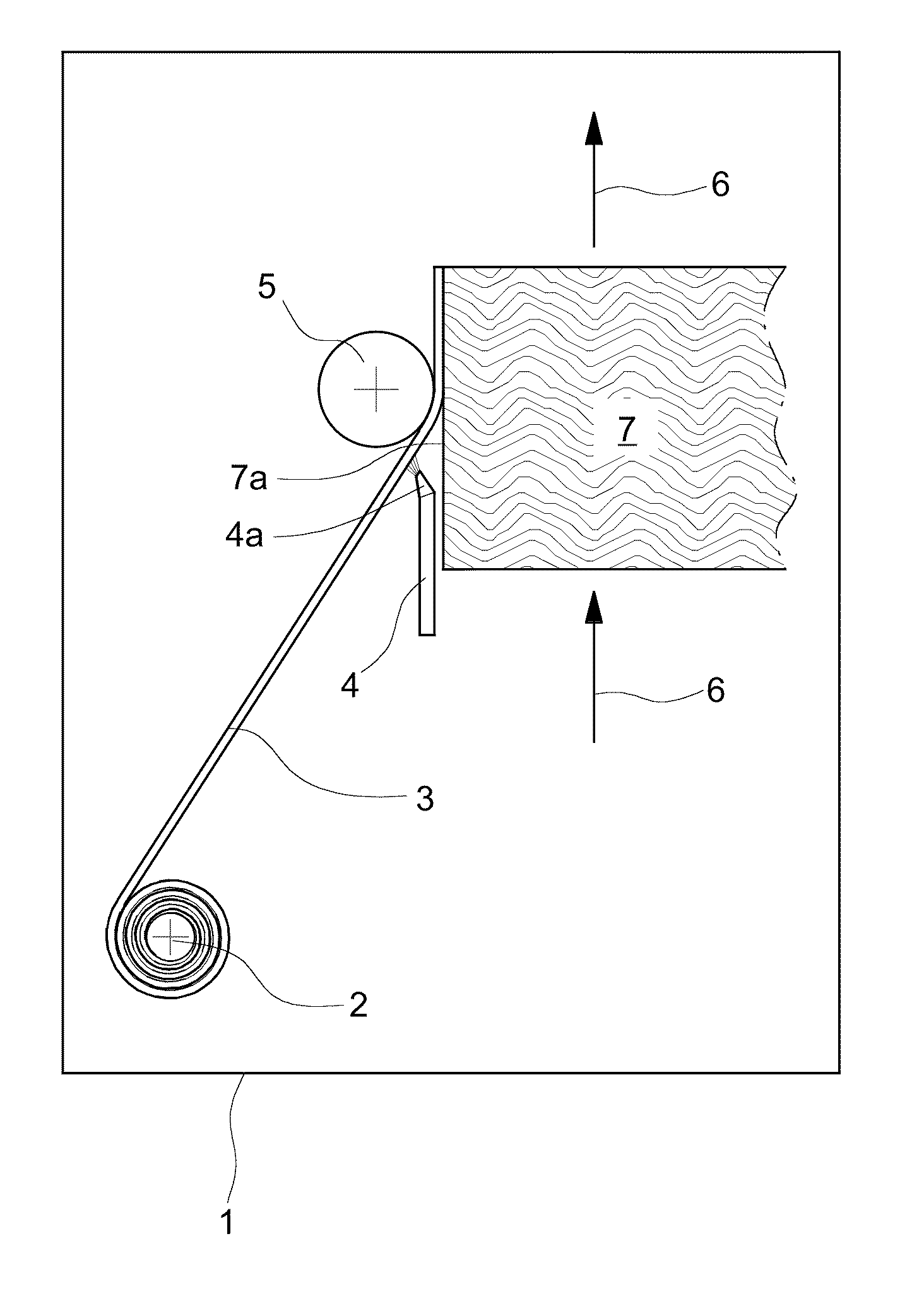
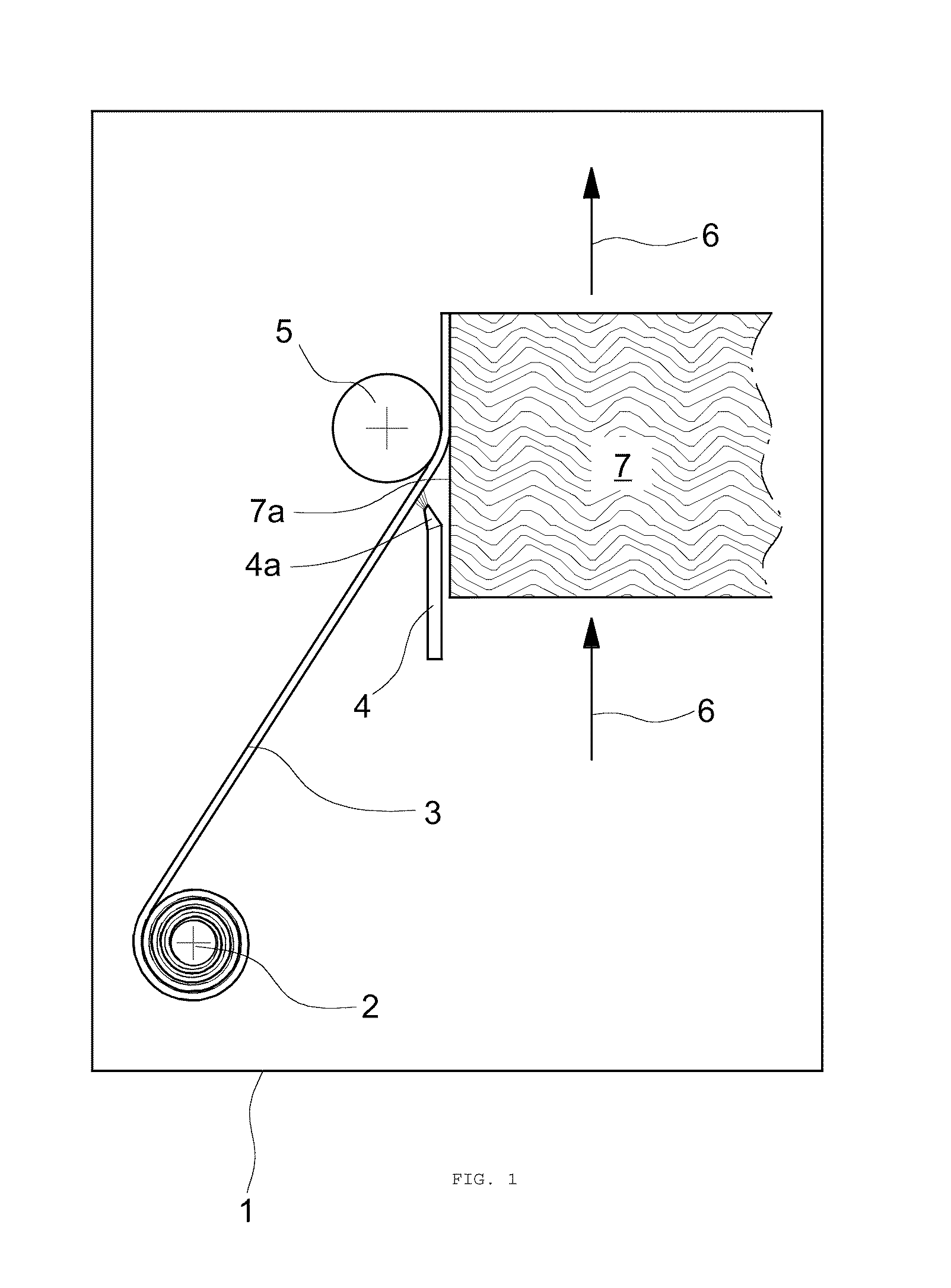
[0020]The present invention accordingly provides—in accordance with a first aspect of the present invention—a method for attaching an edge band (edge strip) to at least one narrow face (narrow side) of an in particular panellike workpiece (material part) by jointing, the edge band being provided on its side to be joined to the workpiece (contact side) with a heat-activatable adhesive layer which is heated by irradiation prior to jointing, where in accordance with the invention the heat-activatable adhesive layer is of plasma-activatable form, in particular the heat-activatable adhesive layer is provided with at least one energy-absorbing and / or thermally conducting substance, and where, in accordance with the invention, the heating of the heat-activatable adhesive layer takes place by means of plasma irradiation.

[0021]The concept of jointing in the context of the present invention refers in particular to methods which cause formerly separate workpieces to cohere, producing a new wor...


PUM

PropertyMeasurementUnit
Temperatureaaaaaaaaaa
Thicknessaaaaaaaaaa

Abstract

The invention relates to a method for applying edge strips (edge tape) onto narrow surfaces (narrow sides) of plate-shaped work pieces (material parts) by joining, wherein the edge strip is applied with a glue that can be activated by heat and is heated by plasma radiation. The invention further relates to the materials to which edge strips have been applied obtained in said way and to a device for carrying out said method.

Description

CROSS-REFERENCES TO RELATED APPLICATIONS[0001]This application is a National Stage filing of International Application PCT / EP 2009 / 004859, filed. Jul. 6, 2009, entitled “METHOD FOR APPLYING EDGE STRIPS ONTO NARROW SURFACES OF IN PARTICULAR PLATE-SHAPED WORK PIECES AND WORK PIECES OBTAINED IN SAID MANNER” claiming priority to German Application No. DE 10 2008 034 115.0, filed Jul. 21, 2008. The subject application claims priority to PCT / EP 2009 / 004859, and to German Application No. DE 10 2003 034 115.0, and incorporates all by reference herein, in their entirety.BACKGROUND OF THE INVENTION[0002]The present invention relates to the technology of attaching edge bands to the surface of workpieces.[0003]More particularly the present invention relates to a method of attaching an edge band to at least one narrow face of an in particular panellike workpiece by jointing, and also to the workpieces obtainable by the method of the invention and to apparatus for carrying cut the method of the i...

Claims


Application Information

Patent Timeline
IPC IPC(8): B32B3/08B32B37/02B32B37/06B32B37/12B32B37/14
CPCB27D5/003Y10T428/24777B29C63/0065B29C63/003
Inventor SCHUMACHER, REINHARD
Owner PLASMATREAT GMBH
Learn More