

Regulation valve
- Summary
- Abstract
- Description
- Claims
- Application Information
AI Technical Summary
Benefits of technology
Problems solved by technology
Method used
Image

Examples
Embodiment Construction
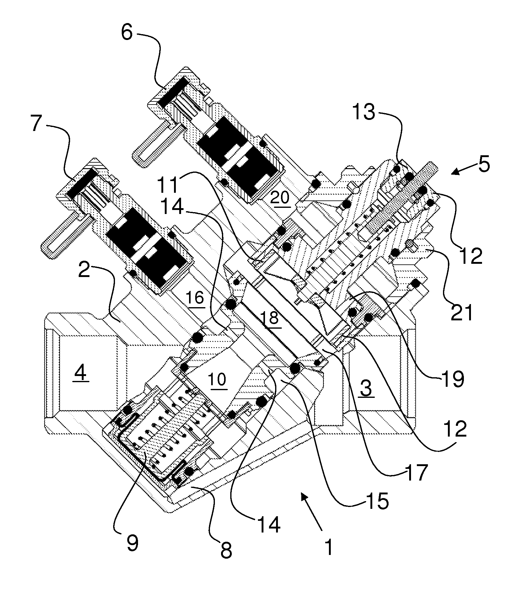
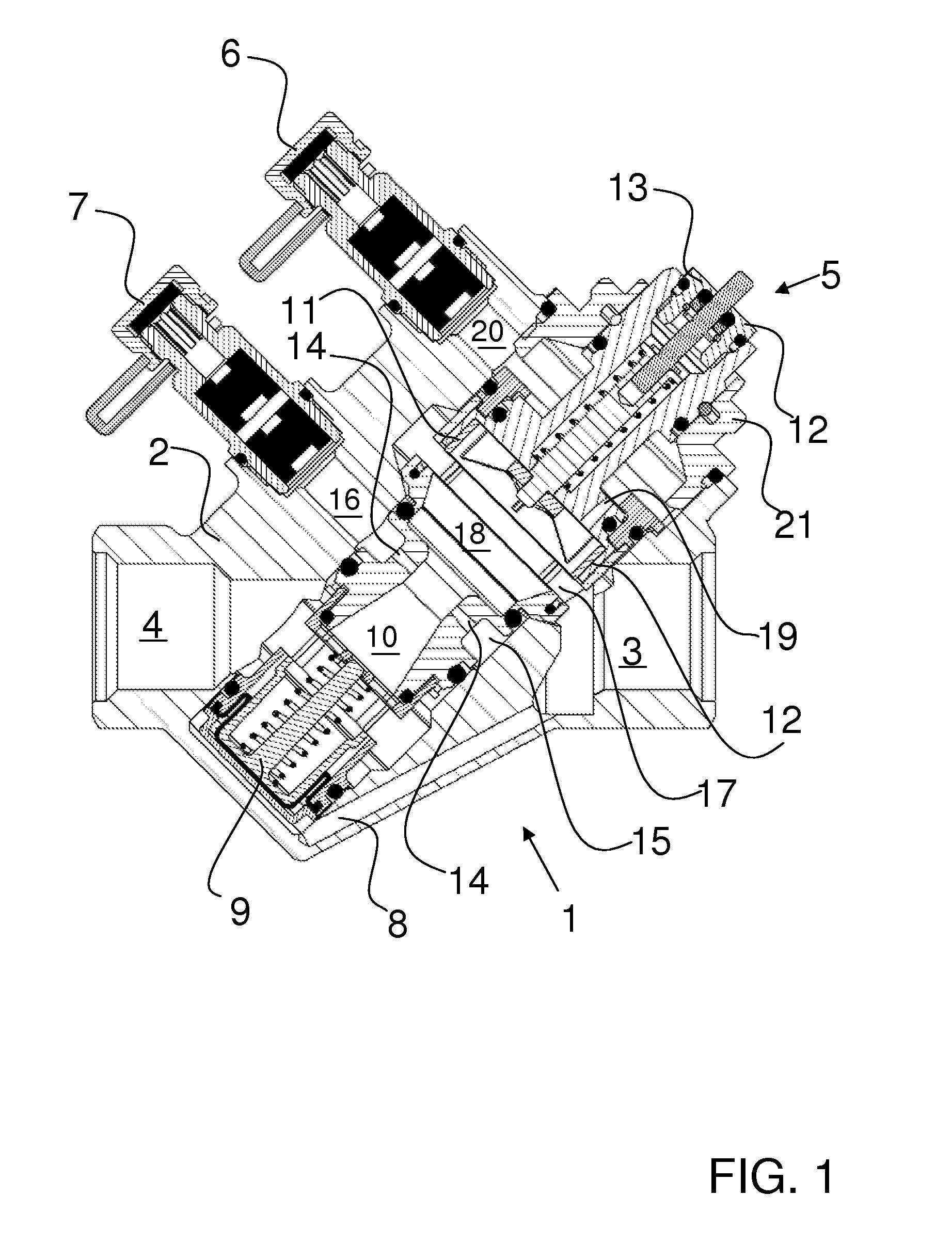
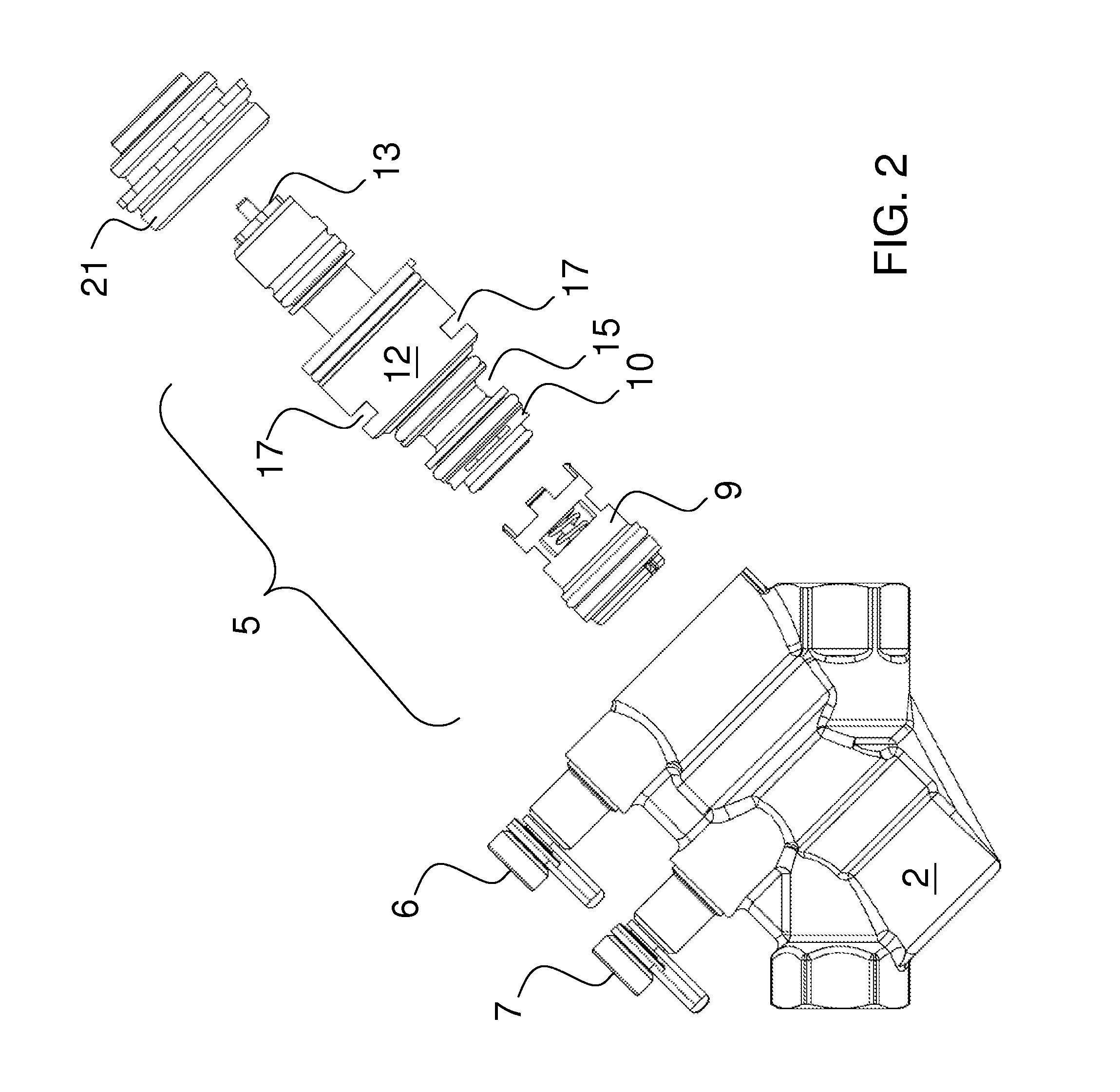
[0006]The invention concerns a regulating valve of the type mentioned in the introduction, wherein the valve insert is modular and is thus at least including a differential pressure regulator, a venturi, a throttle device and a coupling member for an actuator, where the various modules are made with interacting joining means, preferably with snap-action joints.
[0007]By such a valve insert there is achieved the possibility of making a valve insert with exactly the wanted specifications. A valve insert may thus be built up of respective modules, where the modules are selected individually with the specifications most suited for the individual task. It is thus not required to make as many different combinations of valve inserts since they are combined modularly according to need.
[0008]A particularly preferred variant of the invention is where the valve housing of the regulating valve is provided with an inlet communicating with more than one opening in the valve insert, where these ope...
PUM
 Abstract
Description
Claims
Application Information