

Spray discharge assembly
- Summary
- Abstract
- Description
- Claims
- Application Information
AI Technical Summary
Benefits of technology
Problems solved by technology
Method used
Image

Examples
Embodiment Construction
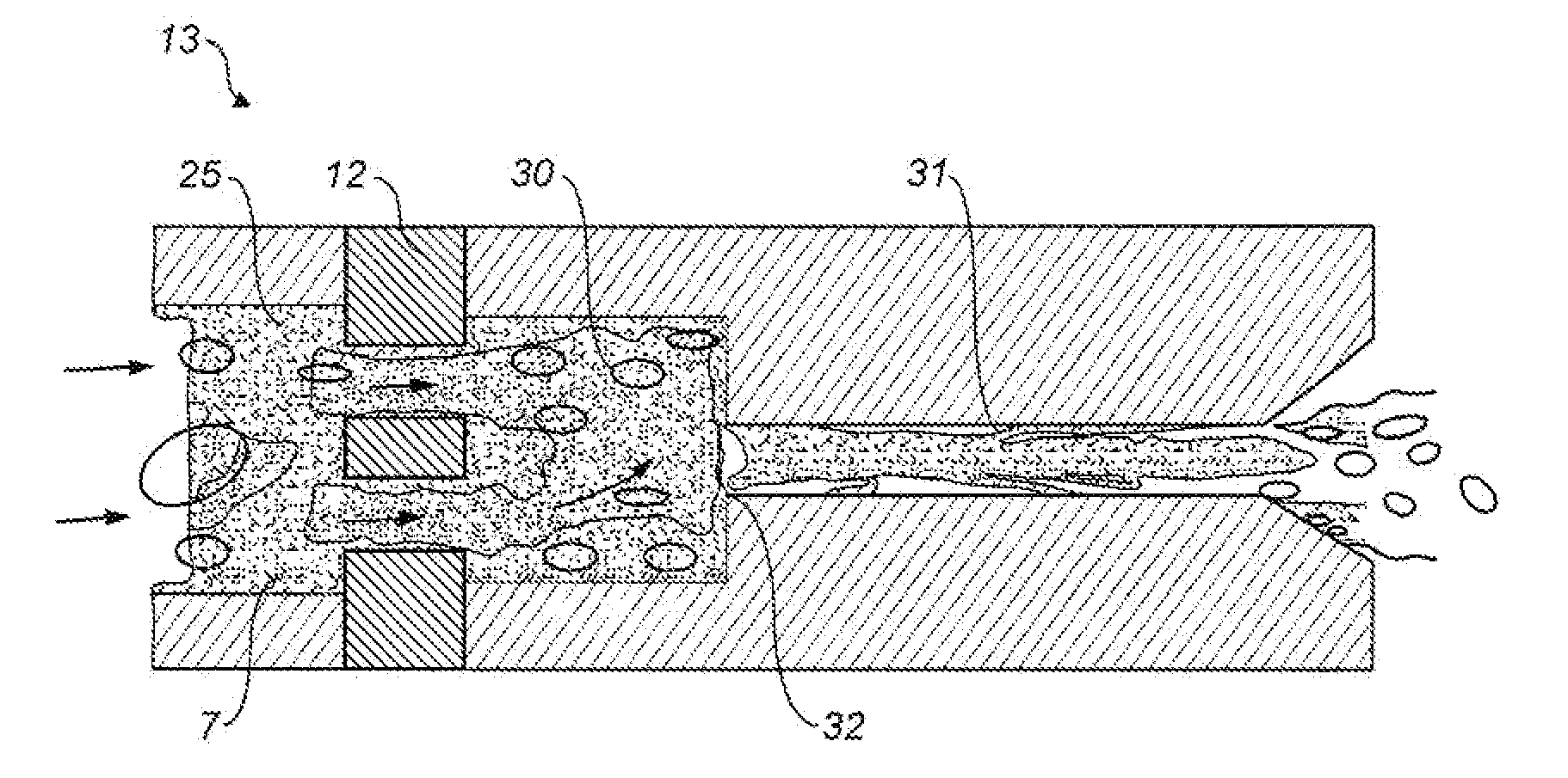
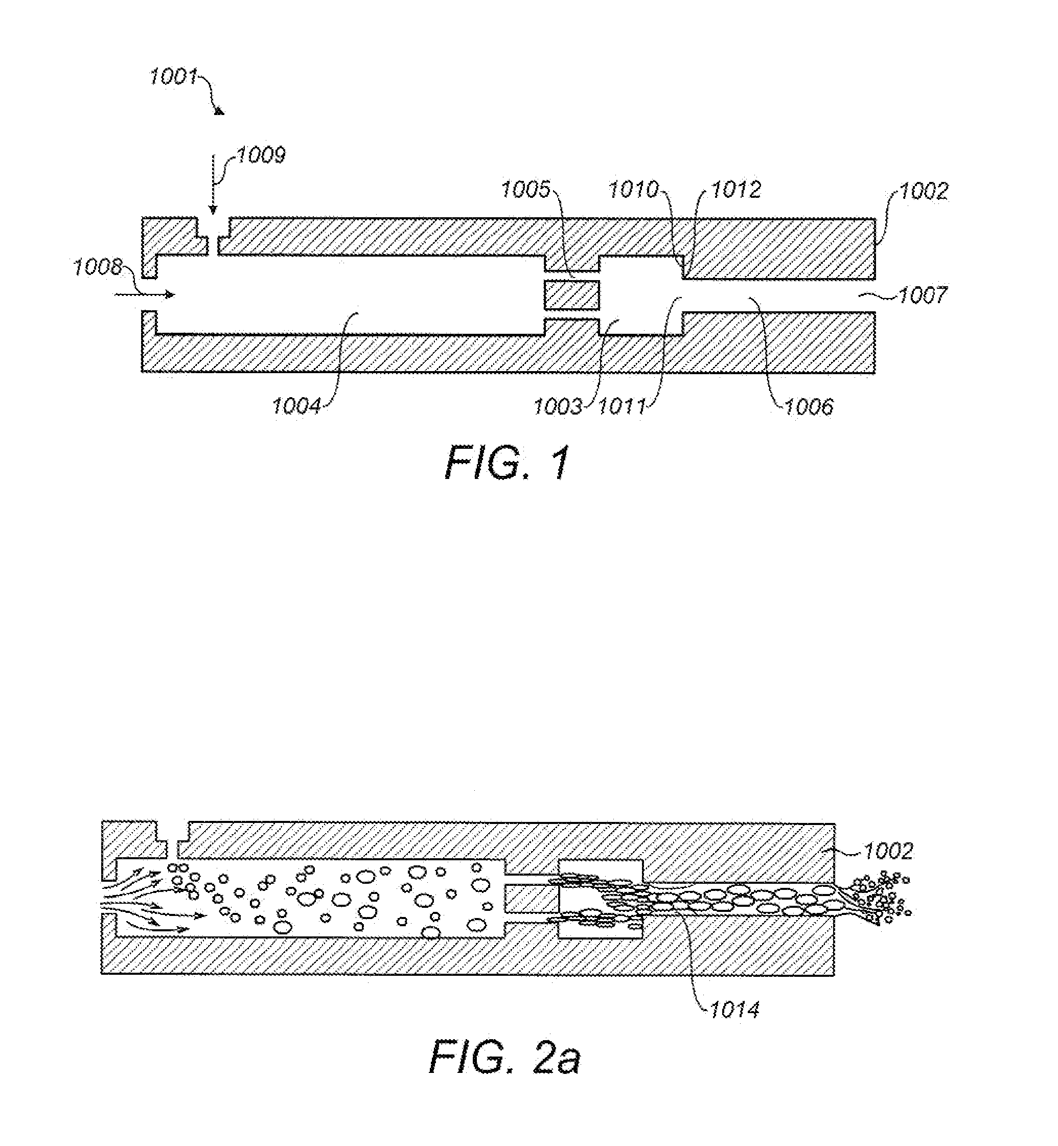
[0047]Reference is made firstly to FIG. 1 which schematically illustrates the principle employed in the invention for causing a liquid held in a pressurised aerosol container to be discharged as a fine spray.
[0048]FIG. 1 shows an outlet arrangement 1001 for an aerosol can (not shown in detail in FIG. 1). As illustrated in FIG. 1, the outlet arrangement 1001 is shown as a one-piece component. However this is purely for the purposes of simplicity and it will be appreciated (and as illustrated in the embodiments shown in FIG. 3 onwards) that outlet arrangement 1001 may be formed from individual components that assemble together to provide the same function as the one-piece outlet arrangement 1001.
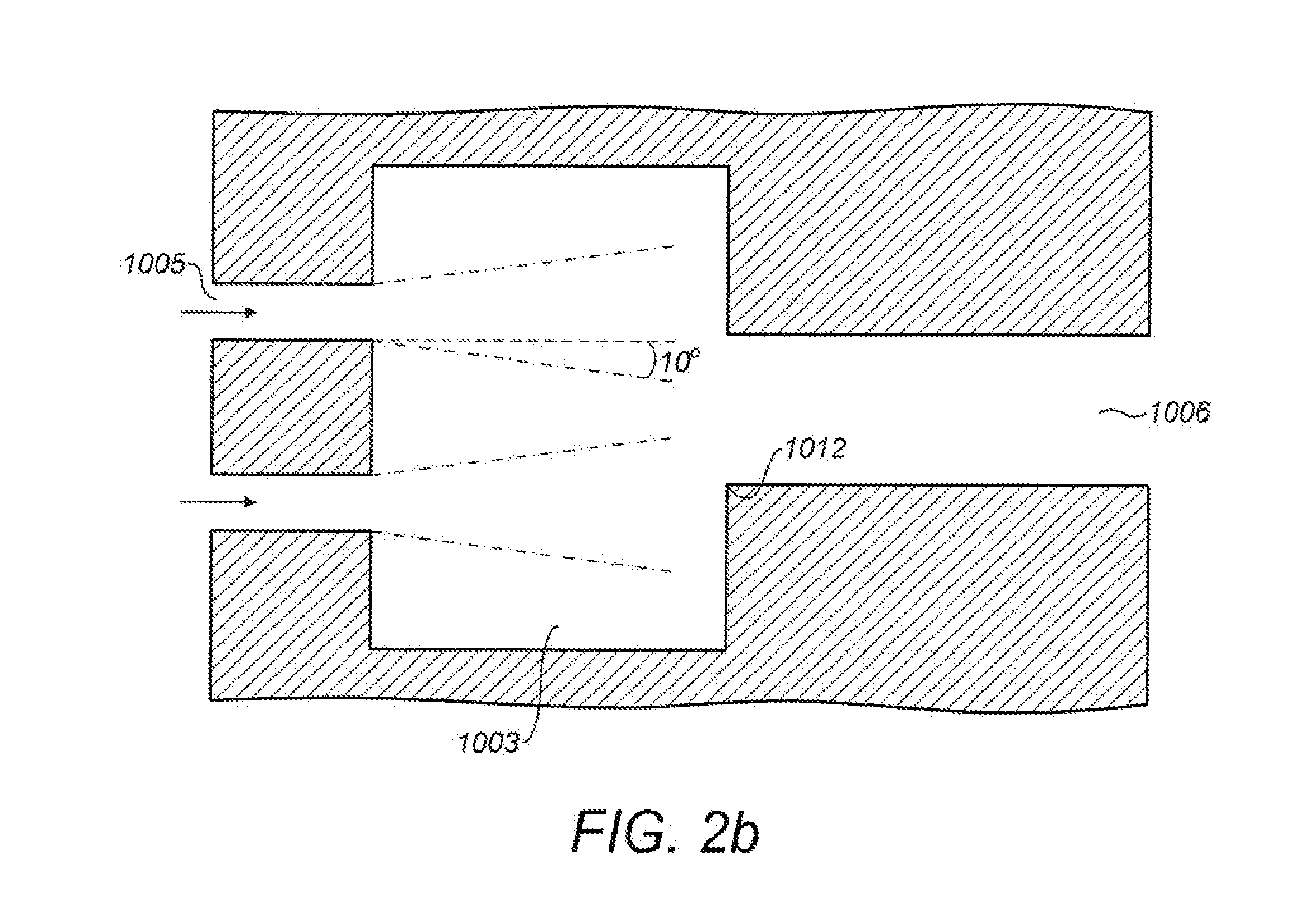
[0049]Outlet arrangement 1001 is comprised of a body 1002 internally configured to define a cylindrical approach channel 1003 communicating with an elongate, cylindrical flow conduit 1004 via jetting orifices 1005 and having a discharge orifice 1006 from the outlet end of 1007 of which (the ri...
PUM
 Abstract
Description
Claims
Application Information