Check patentability & draft patents in minutes with Patsnap Eureka AI!

Inductive touch key switch system, assembly and circuit

a touch key switch and touch key technology, applied in the field can solve the problems of increased noise/decreased signal strength problems, crosstalk and signal strength loss in the circuit, and the impracticality of sensing coil diameter for the landscape of the device keyboard, so as to improve the effect of inductive touch key switch

Inactive Publication Date: 2011-08-04
DIEHL AKO STIFTUNG
View PDF3 Cites 29 Cited by
  • Summary
  • Abstract
  • Description
  • Claims
  • Application Information

AI Technical Summary

Benefits of technology

[0008]It is accordingly an object of this invention to provide an inductive touch key switch and circuit that overcomes the disadvantages of the prior art. In one particular embodiment of the invention, an improved indu

Problems solved by technology

Such a sensing coil diameter would be impractical for the landscape of the device keyboard, i.e., requiring a key spacing of more than 2 inches.
However, higher drive currents in the large drive loops on the PCB can cause crosstalk and loss of signal strength in the circuit.
Additionally, the circuit loops can pick up signals from external fields (i.e., large loops on the PCB layout pick up noise signals).
This increased noise / decreased signal strength problems are even further exacerbated when a keyboard is long, rather than of a small, square shape.
However, the MICROCHIP Design specifically discloses that such software can become complex and can significantly increase the burden on the microcontroller, whereas the inclusion of the reference inductor on the board is minimal and, therefore, the MICROCHIP Design specifically states that omitting the reference coil is not recommended, once the increase in software complexity is considered.

Method used


Image

  • Inductive touch key switch system, assembly and circuit
  • Inductive touch key switch system, assembly and circuit
  • Inductive touch key switch system, assembly and circuit

Examples


Embodiment Construction

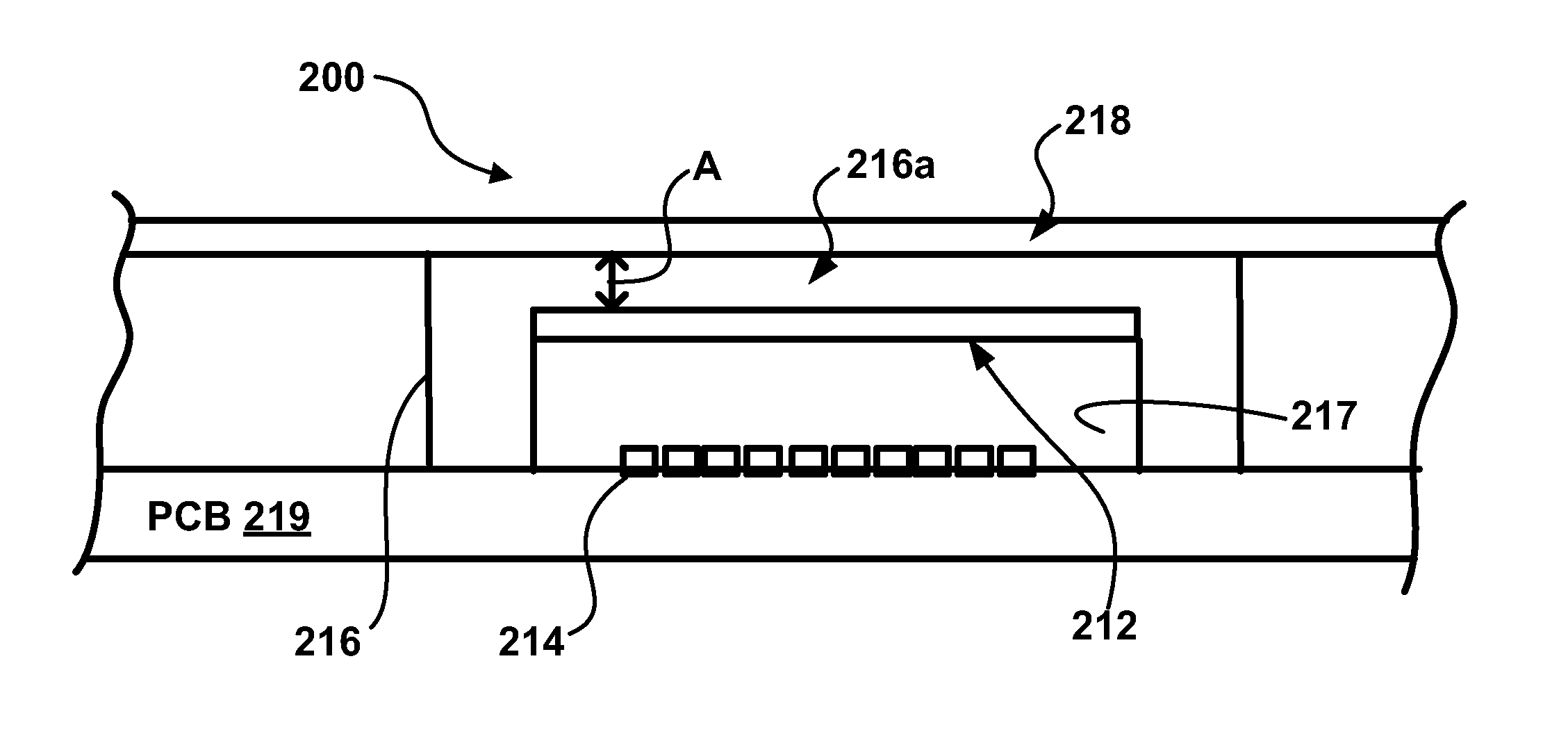
[0035]An inductive touch key switch assembly and circuit are provided herein, which, under certain circumstances, can be used to improve both the signal strength and the noise immunity of the instant invention over that of the MICROCHIP Design.

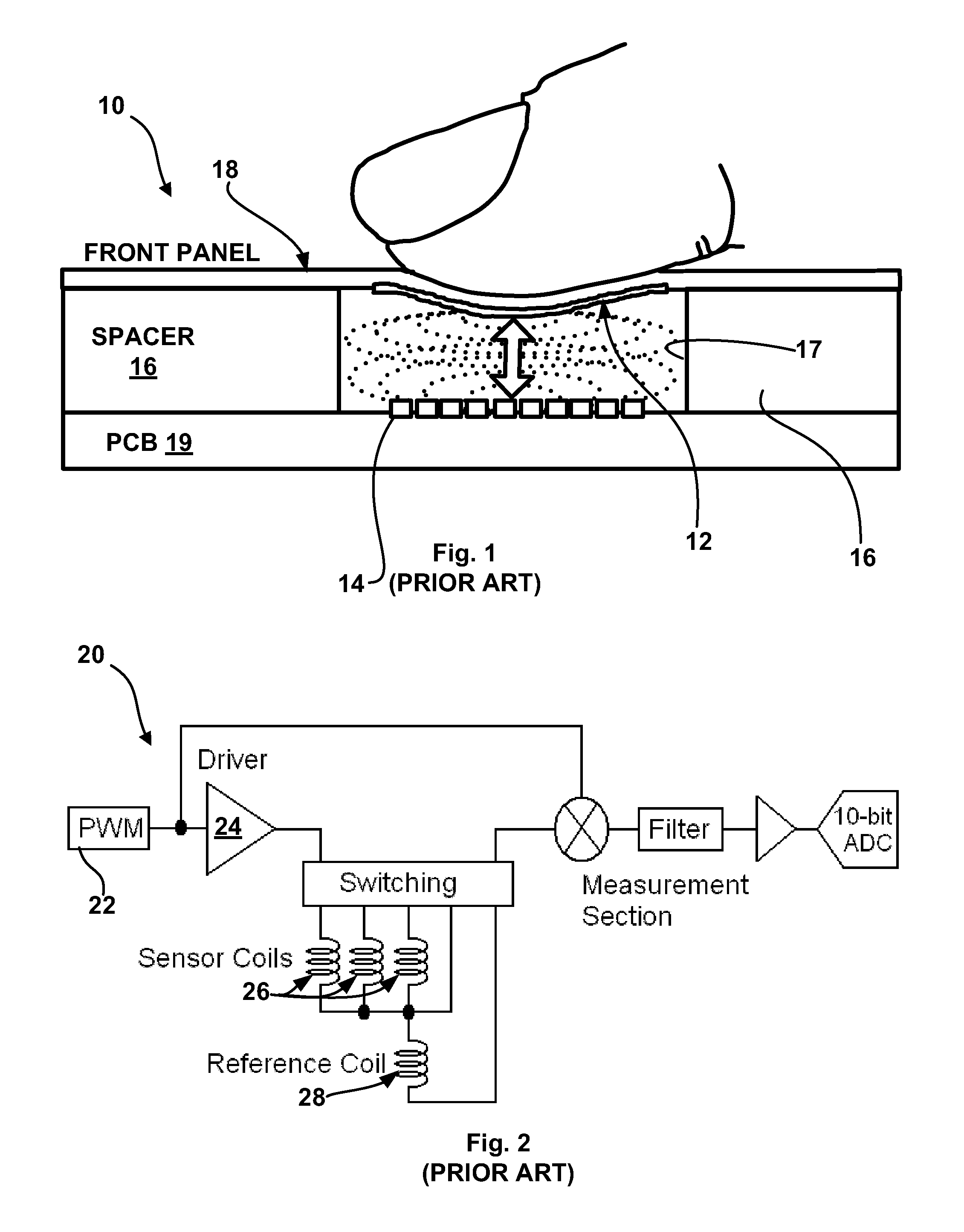
[0036]Referring more particularly to FIG. 2, there is shown a block diagram of a prior art inductive touch key switch system 20 in accordance with the teachings of the MICROCHIP Design. In order to measure the impedance of an individual sensor or sensing coil 26, the system 20 produces a pulse at the pulse width modulator (PWM) 22, which is converted into a drive pulse by the driver 24 that is used to excite, in turn, each individual sensor coil 26. This produces a pulsed voltage across the excited sensor coil 26 that is proportional to both the current and the impedance of the coil 26. The pulsed voltage from the sensor coil 26 is further processed and analyzed to determine whether a shift in impedance has occurred, indicating a user's touch....


PUM


Abstract

An inductive touch key switch assembly and circuit are provided. The circuit optimizes signal strength and noise immunity by reducing the number of long paths through the circuit board and localizes the driver circuit to each key switch assembly sensor coil. The key switch assembly optimizes placement of the target to enable the user interfaces on domestic appliances and products having present values of front panel thickness.

Description

FIELD OF THE INVENTION[0001]The instant invention relates to an inductive touch key switch and its associated control circuit, wherein the inductive touch key switch user interface is adapted for use with a control circuit having drive elements localized to each key switch.DESCRIPTION OF THE RELATED ART[0002]Generally, inductive touch key switches and circuits are known. For example, referring now to FIG. 1, MICROCHIP TECHNOLOGY INC. (“MICROCHIP”) of Chandler, Ariz. has published an inductive touch key switch assembly design 10 (the “MICROCHIP Design”) that uses a magnetic coupling between a solid metal target 12 and an inductive sensing or sensor coil 14, separated from one another by a spacer layer 16. The spacer layer 16 defines a cavity or pocket into which the solid metal target 12 can flex when pressed, thus changing the proximity to, and the field around, the sensor coil 14, which is mounted to, printed on and / or etched into a printed circuit board PCB 19. More particularly, ...

Claims


Application Information

Patent Timeline
IPC IPC(8): H01H33/59
CPCH03K17/96H03K2217/96038H03K2017/9706
Inventor LACEY, KEVINKOPEC, JAMESALVORD, ROBERTKAPS, WERNERJOHANSEN, SCOT
Owner DIEHL AKO STIFTUNG
Features
  • R&D
  • Intellectual Property
  • Life Sciences
  • Materials
  • Tech Scout
  • Unparalleled Data Quality
  • Higher Quality Content
  • 60% Fewer Hallucinations
Learn More