
Optical fiber coatings for reducing microbend losses

a technology of optical fiber and microbend, applied in the field of optical fiber coatings, can solve the problems of signal loss, bandwidth-limiting polarization mode dispersion in the telecommunication system, and microbends can also arise, and achieve the effect of reducing microbend losses

Inactive Publication Date: 2011-08-04
OFS FITEL LLC
View PDF12 Cites 21 Cited by
  • Summary
  • Abstract
  • Description
  • Claims
  • Application Information

AI Technical Summary

Benefits of technology

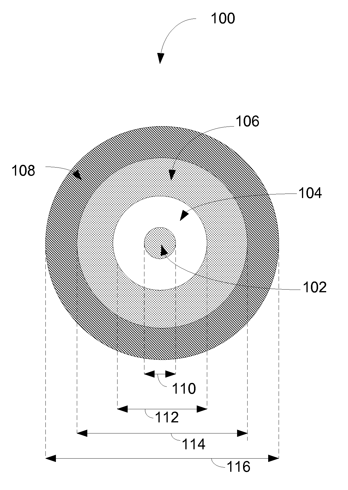
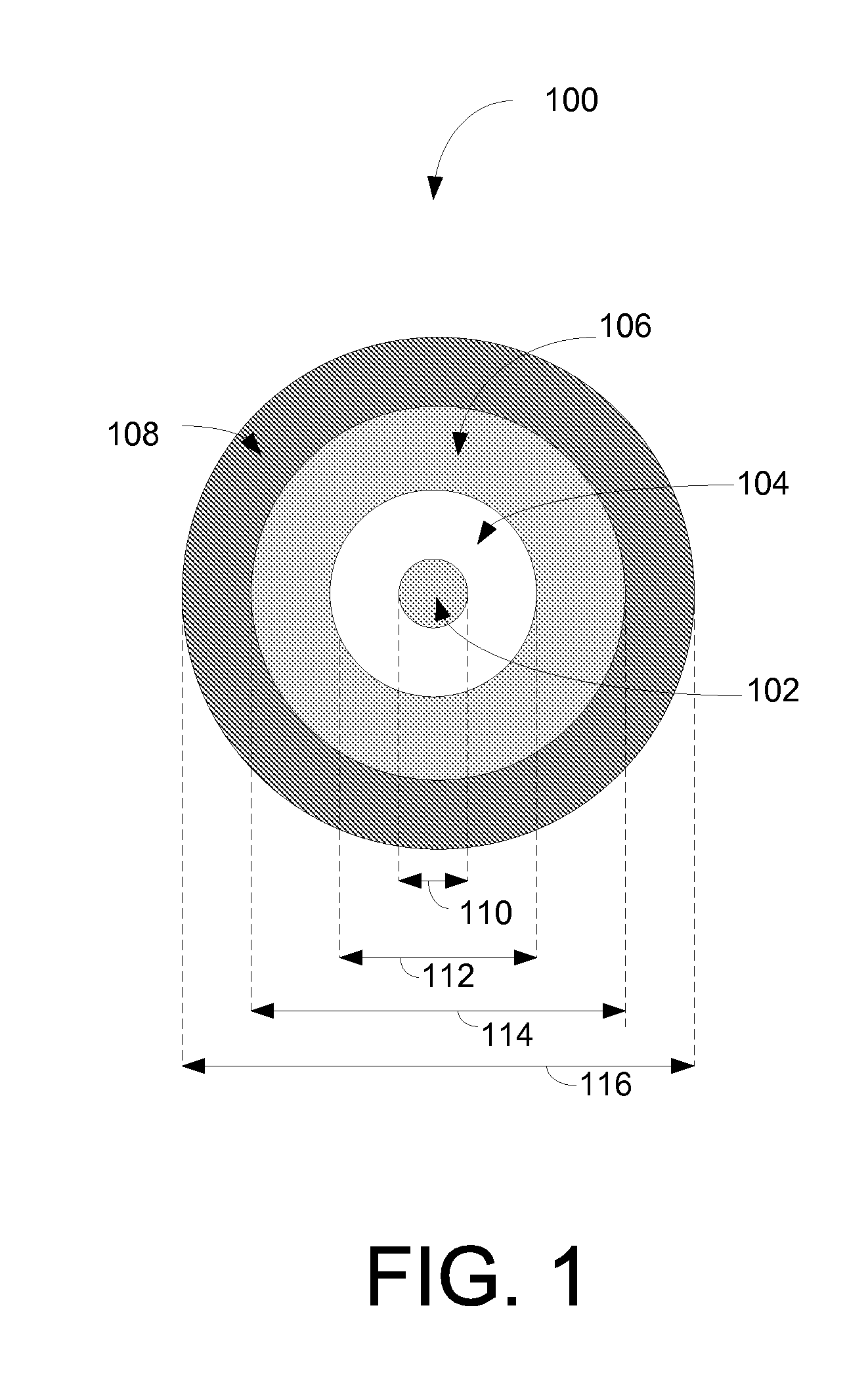
[0008]Some or all of the above needs may be addressed by certain embodiments of the invention. Certain embodiments of the invention may include systems, methods, and apparatuses related to optical fiber coatings for reducing microbend losses.
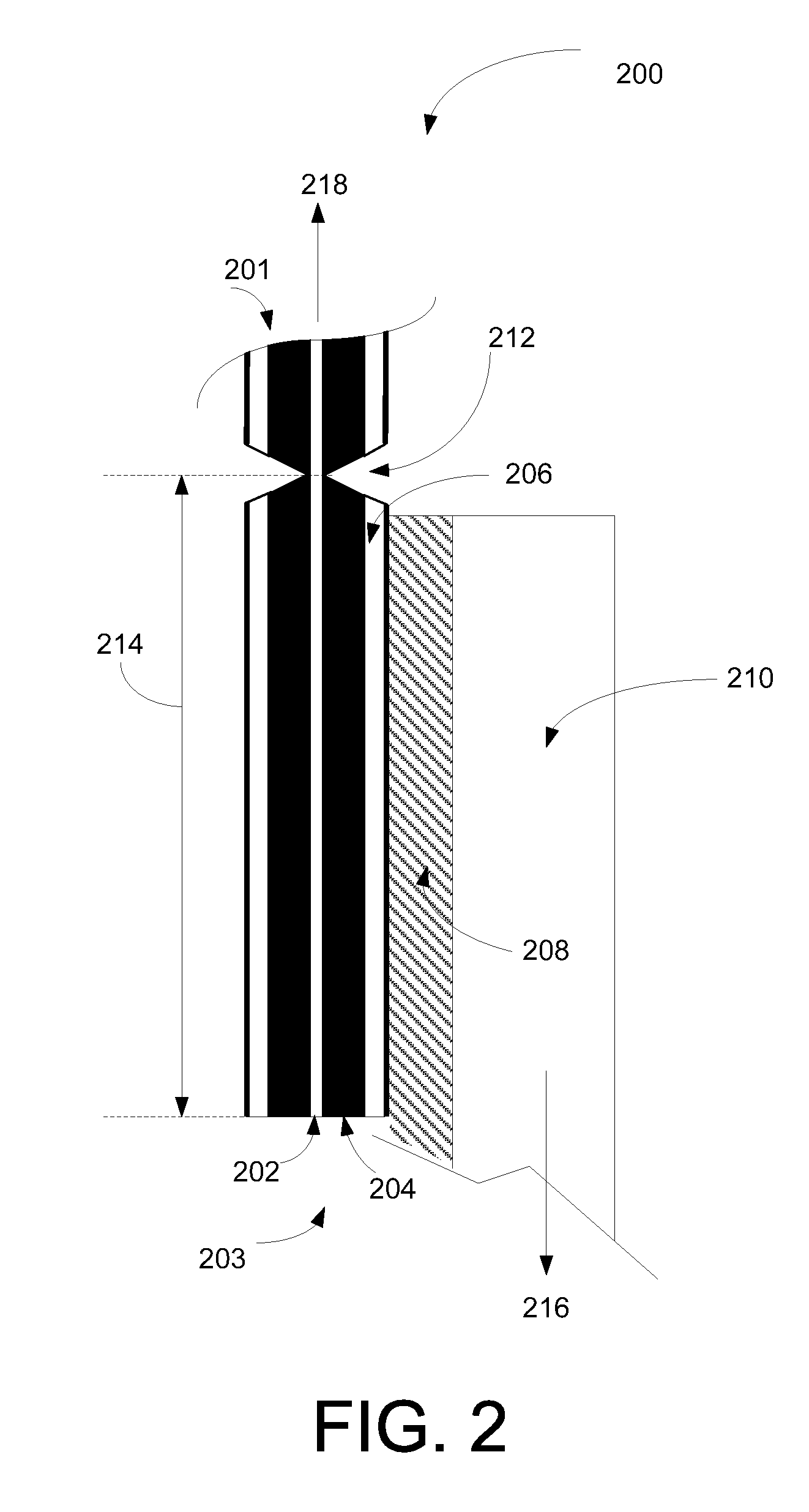
[0010]According to another example embodiment, a system for coating an optical fiber to reduce microbend losses and polarization mode dispersion is provided. The system includes a first reservoir containing a primary layer material, and a primary die for applying the primary layer to an optical fiber, wherein the optical fiber comprises a core region surrounded by a cladding region, and wherein the primary layer, once cured, adheres to the cladding region with a minimum pullout adhesion of 6 N / cm. The system also includes a second reservoir containing a secondary layer material, and a secondary die for applying the secondary layer to the primary layer, wherein the secondary layer, once cured, has an in situ modulus of about 700 MPa to about 1200 MPa at room temperature. The system may also include a curing lamp system for curing the primary and secondary layers.
[0011]According to another example embodiment, a method is provided for coating an optical fiber to reduce microbend losses and polarization mode dispersion (PMD). The method may include applying a primary layer to an optical fiber, wherein the optical fiber comprises a core region surrounded by a cladding region, applying a secondary layer to the primary layer, and curing the primary and secondary layers, wherein the cured primary layer adheres to the cladding region with a minimum pullout adhesion of 6 N / cm, and the cured secondary layer has an in situ modulus of about 700 MPa to about 1200 MPa at room temperature.

Problems solved by technology

However, mechanical forces acting on the optical fiber can create small deformations in the glass fiber pathway and can cause light propagation modes to couple into the cladding, resulting in signal losses.
Furthermore, deformations in the optical fiber can create eccentricities in the fiber core and can cause propagation velocity mismatches between polarization modes in the optical fiber, which can lead to bandwidth-limiting polarization mode dispersion in the telecommunication system.
However, microbending can also arise from internal forces, including irregularities in the fiber coatings, and expansion coefficient mismatches between the glass core, the cladding, and the surrounding coatings.
In routine fiber installations, microbending can significantly attenuate the transmission of light in the fiber, and in some cases, the additional attenuation can be very costly.
For example, transoceanic channels utilize amplifiers to regenerate attenuated light signals, and microbend losses in the fiber can necessitate an increase in the number of signal amplifying transceivers required, thereby resulting in significant added costs in terms of system components, installation, and maintenance.
However, not all installations can utilize the loose tube method, and therefore, the coatings applied directly to the fiber must be relied upon to provide isolation from mechanical stresses.
Unfortunately, further attempts at reducing microbend losses by creating a more pliable primary coating can lead to durability-related issues, such as delamination and fiber buckling.

Method used


Image

  • Optical fiber coatings for reducing microbend losses
  • Optical fiber coatings for reducing microbend losses
  • Optical fiber coatings for reducing microbend losses

Examples


Embodiment Construction

[0021]Embodiments of the invention will be described more fully hereinafter with reference to the accompanying drawings, in which embodiments of the invention are shown. This invention may, however, be embodied in many different forms and should not be construed as limited to the embodiments set forth herein; rather, these embodiments are provided so that this disclosure will be thorough and complete, and will fully convey the scope of the invention to those skilled in the art. Like numbers refer to like elements throughout. Certain embodiments of the invention may enable a reduction in optical fiber microbend losses while maintaining durability.

[0022]Conventional methods for reducing microbend losses have been predominantly focused on reducing the modulus of the primary coating. However, reducing the modulus of the primary coating can reduce the strip force, and can cause delamination and coating separation during standard tensile strength testing, and also during handling of the o...


PUM

PropertyMeasurementUnit
Pressureaaaaaaaaaa
Pressureaaaaaaaaaa
Pressureaaaaaaaaaa

Abstract

Certain embodiments of the invention may include systems and methods for providing optical fiber coatings to reduce microbend losses. According to an example embodiment of the invention, a method is provided for coating an optical fiber to reduce microbend losses and polarization mode dispersion (PMD). The method includes applying a primary layer to the optical fiber, wherein the optical fiber comprises a core region surrounded by a cladding region. The method includes applying a secondary layer to the primary layer, and curing the primary and secondary layers, wherein the cured primary layer adheres to the cladding region with a minimum pullout adhesion of 6 N / cm, and the cured secondary layer has an in situ modulus of about 700 MPa to about 1200 MPa at room temperature.

Description

FIELD OF THE INVENTION[0001]This invention generally relates to optical fiber coatings, and in particular, to optical fiber coatings for reducing microbend losses.BACKGROUND OF THE INVENTION[0002]Optical fibers are often utilized in telecommunication systems that require wide bandwidth and low transmission losses. However, mechanical forces acting on the optical fiber can create small deformations in the glass fiber pathway and can cause light propagation modes to couple into the cladding, resulting in signal losses. Furthermore, deformations in the optical fiber can create eccentricities in the fiber core and can cause propagation velocity mismatches between polarization modes in the optical fiber, which can lead to bandwidth-limiting polarization mode dispersion in the telecommunication system.[0003]The loss mechanism in the optical fiber that is associated with very small deformations of the core occurring at length scales (along the fiber) of hundreds of microns is often referre...

Claims


Application Information

Patent Timeline
IPC IPC(8): G02B6/02B05C1/04B05D5/06
CPCG02B6/02395C03C25/1065
Inventor KONSTADINIDIS, KARIOFILISGARNER, HARRYHASLOV, PETERKIM, JINKEESIMOFF, DEBRAVAIDYA, DURGESHARASHITANI, YOSHIHIRO
Owner OFS FITEL LLC
Learn More