Photoacoustic imaging devices and methods of making and using the same

a technology of photoacoustic imaging and imaging device, which is applied in the field of photoacoustic imaging, can solve the problems of inability to detect small tumors with diameters less than 4 mm at their earliest stages, unsuitable end user setup, and inability to perfect,

Active Publication Date: 2011-08-04
STC UNM
View PDF7 Cites 60 Cited by
  • Summary
  • Abstract
  • Description
  • Claims
  • Application Information

AI Technical Summary

Problems solved by technology

While useful as a laboratory platform, this setup is not suitable for an end user like a medical doctor for general clinical use.
While mammography is the only breast cancer screening method that has been shown to save lives, it is not perfect and has its limitations.
Mammography cannot detect small tumors with diameters less than 4 mm at their earliest stages.
Also, because the X-ray contrast between the early tumor tissue and normal tissue types is low, it is hard for the mammography to detect the early stage tumors.
The technique is further challenged by the age of the woman; younger women have denser breast tissue, making masses harder to detect.
Second, mammography often fails to differentiate conclusively between malignant and benign masses (false positive) which will cause women to undergo unnecessary medical intervention and undue stress.
When the shape is very ugly, it is a strong indication of malignancy.
While irregular blood vessel distribution and blood oxygen concentration provide the surest indication of breast cancer, conventional X-ray-based mammography or ultrasound imaging cannot distinguish blood from tissue and therefore would miss this valuable diagnostic information.
While magnetic resonance imaging (MRI) is capable of capturing the image of blood, the equipment and operation cost of MRI is too expensive for regular annual breast screenings, which are recommended for women above the age of 40.
One of the current limitations of PAI for general clinical use is developing the technology and hardware that would provide fast, real-time anatomical or functional images.
Manual alignment / adjustment is time consuming and does not always produce satisfactory results.
In addition, few existing systems allow for full parallel receive that would provide a 3D image from a single laser pulse.
However, the device performance of the piezoelectric ultrasonic transducer in medical applications is limited by the material properties and related electrical and acoustic impedance match issues.

Method used


Image

  • Photoacoustic imaging devices and methods of making and using the same
  • Photoacoustic imaging devices and methods of making and using the same
  • Photoacoustic imaging devices and methods of making and using the same

Examples


Embodiment Construction

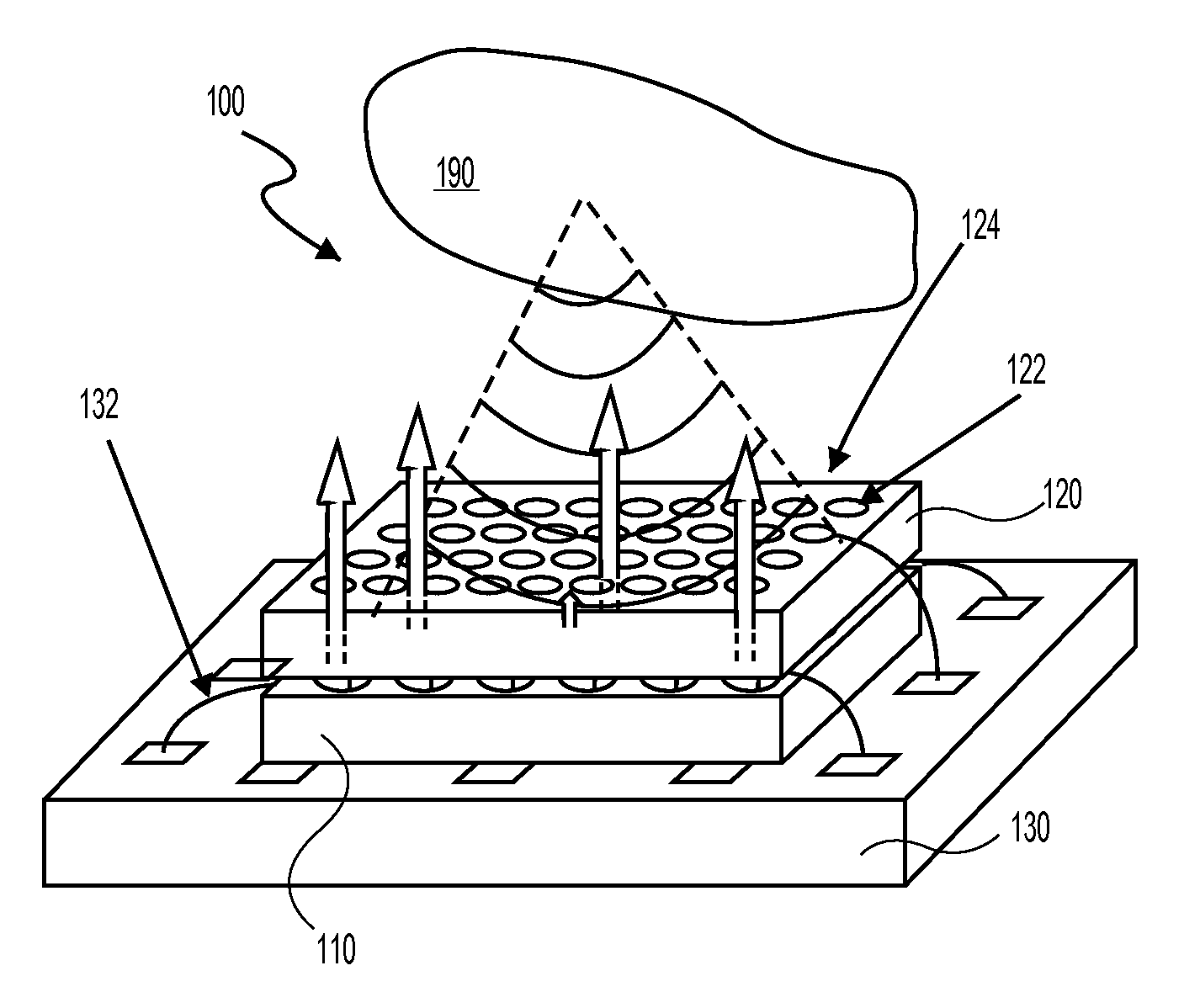
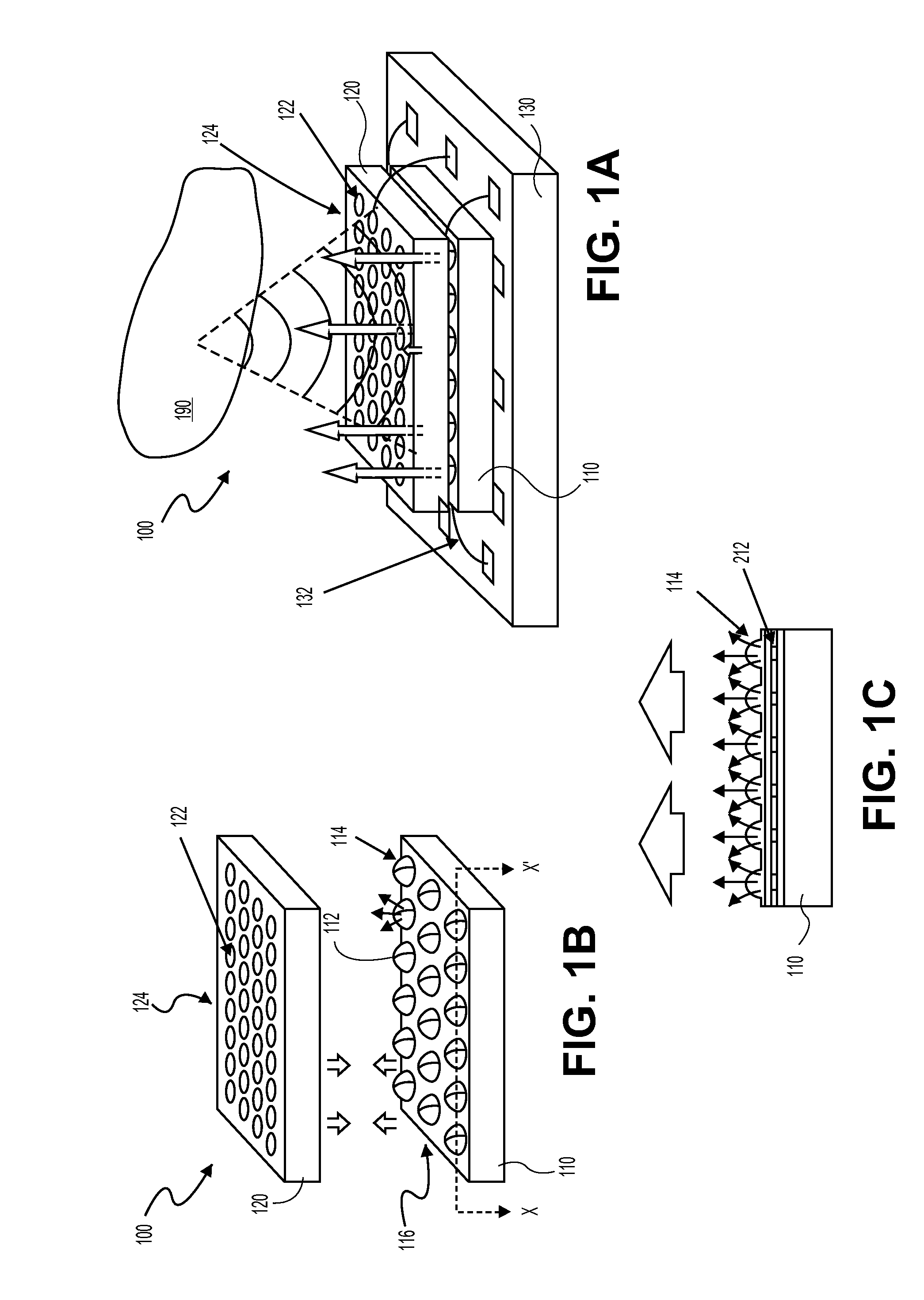
[0046]An exemplary embodiment of a photoacoustic imaging device with integrated arrays of infrared light sources and ultrasonic transducers is shown in FIGS. 1A-1C. According to various aspects of the disclosure, a photoacoustic imaging device 100 may comprise a first substrate 110 and a second substrate 120, with the second substrate 120 being stacked on the first substrate 110 and coupled to one another, for example, via wafer-to-wafer bonding. The stacked substrates 110, 120 may be electrically coupled with a printed circuit board 130 via bonding wire 132.

[0047]Ultrasonic transducers 122 may be integrated on the second substrate 120 in a one- or two-dimensional array 124. The second substrate 120 may comprise an infrared-transparent substrate such as, for example, silicon, glass, or polymer, such that infrared light illuminated from underneath the ultrasonic transducer substrate 120 can penetrate through the ultrasonic transducer substrate 120 and cast on target tissue without si...


PUM


Abstract

A photoacoustic imaging device includes an array of light sources configured and arranged to illuminate a target region and an array of ultrasonic transducers between the array of light sources and the target region. The array of transducers may be fixedly coupled to the array of light sources, and the array of ultrasonic transducers may be configured and arranged to receive ultrasound transmissions from the target region.

Description

CROSS-REFERENCE TO RELATED APPLICATIONS[0001]This application is related to U.S. provisional patent application No. 61 / 057,569, entitled “PHOTOACOUSTIC IMAGING DEVICES AND METHODS OF MAKING AND USING THE SAME,” filed on May 30, 2008, and U.S. provisional patent application No. 61 / 100,981, entitled “PHOTOACOUSTIC IMAGING MODULES,” filed on Sep. 29, 2008, the contents of both of which are incorporated herein by reference.TECHNICAL FIELD[0002]The present disclosure relates generally to photoacoustic imaging. More particularly, this disclosure relates to photoacoustic imaging devices, including photoacoustic modules having a light source and an ultrasonic transducer array, and methods of imaging with these devices.BACKGROUND[0003]Photoacoustic imaging (PAI) makes use of infrared-induced ultrasound for constructing an image of an organ or tissue inside the body. In this process, a short infrared pulse, typically 5-10 ns in width, is used to illuminate the organ or tissue. Upon absorption...

Claims


Application Information

Patent Timeline
Patent Type & Authority Applications(United States)
IPC IPC(8): A61B5/05
CPCA61B5/0091A61B8/483A61B5/4312G01N21/1702G01N29/2406G01N29/2418G01N2021/1706G01N2291/02475G01N2291/106A61B8/4483A61B8/44A61B5/0093A61B5/0048A61B2562/028A61B2562/02G01N29/24A61B5/0095A61B8/4444
Inventor CHEN, JINGKUANG
Owner STC UNM
Why Eureka
Try Eureka