
Distributed data management system

Active Publication Date: 2011-08-04
GOPIVOTAL
View PDF6 Cites 69 Cited by
  • Summary
  • Abstract
  • Description
  • Claims
  • Application Information

AI Technical Summary

Benefits of technology

[0005]In particular, Database Management Systems (DBMs) guarantee that data modifications are strictly serializable and thus require expensive transaction management overhead and distributed locking to insure data correctness. The need for such transaction overhead and locking greatly reduces concurrent data access and limits performance
[0009]The present invention provides equivalent representations of complex data types that result in compressed byte arrays. These compressed data representations are stored and only reified back to their original format as needed. Accordingly, the invention provides data translation and passivation that not only reduce resource storage footprint but also speeds data transfer. The invention provides caching and synchronization of data sets without the expensive node-to-node data transfers that are commonly used. The invention provides scalable data structures, concurrency, efficient serialization and passivation, and data caching that enable applications to store and retrieve data in a manner that is optimal for use in a distributed environment where high speed service delivery and graceful scalability are critical.
[0011]The present invention eliminates the need for the transaction management of conventional systems and maximizes concurrency through a distributed data structure that enables concurrent access to all data at all times, even as the data structure is growing. The disclosed invention overcomes this concurrency limitation with its non-blocking approach to data management while offering the dynamic scalability benefits of SDDS.

Problems solved by technology

In the field of data management, maximizing both scalability and performance at the same time is a challenging problem.
Scalability and performance are often conflicting objectives because improvements in one typically come at the expense of the other.
In a multicomputer environment, where processes are physically distributed, the problem is exacerbated by network latency and communication bandwidth between nodes.
The problem is even more daunting if nodes must join the distributed system in an ad-hoc fashion without service interruption.
Prior solutions provide high scalability at the expense of low performance or vice versa.
In particular, Database Management Systems (DBMs) guarantee that data modifications are strictly serializable and thus require expensive transaction management overhead and distributed locking to insure data correctness.
The need for such transaction overhead and locking greatly reduces concurrent data access and limits performance
Prior Scalable Distributed Data Structures (SDDS) solutions offer dynamic data scalability in a multicomputer environment, but encounter vexing performance problems that limit operational utility.
Like distributed DBMS solutions, existing SDDS solutions inevitably encounter performance bottlenecks when accessed by a plurality of concurrent users.
Though SDDS solutions can load balance data uniformly across multiple computer nodes, access to data on a particular node can be blocked undesirably by concurrent requests.
SDDS solutions also encounter performance limitations when managing data with complex shapes or of large size.
Data sets composed of complex relationships form deep object graphs that incur expensive serialization costs.
Compared to primitive data types, the computational cost of serializing and deserializing a complex object graph is significant.
Because large objects consume significant network bandwidth and result in undesirable transfer latency, SDDS solutions inevitably encounter performance bottlenecks because they must repeatedly drag large objects across the network for every remote request.

Method used


Image

  • Distributed data management system
  • Distributed data management system
  • Distributed data management system

Examples


Embodiment Construction

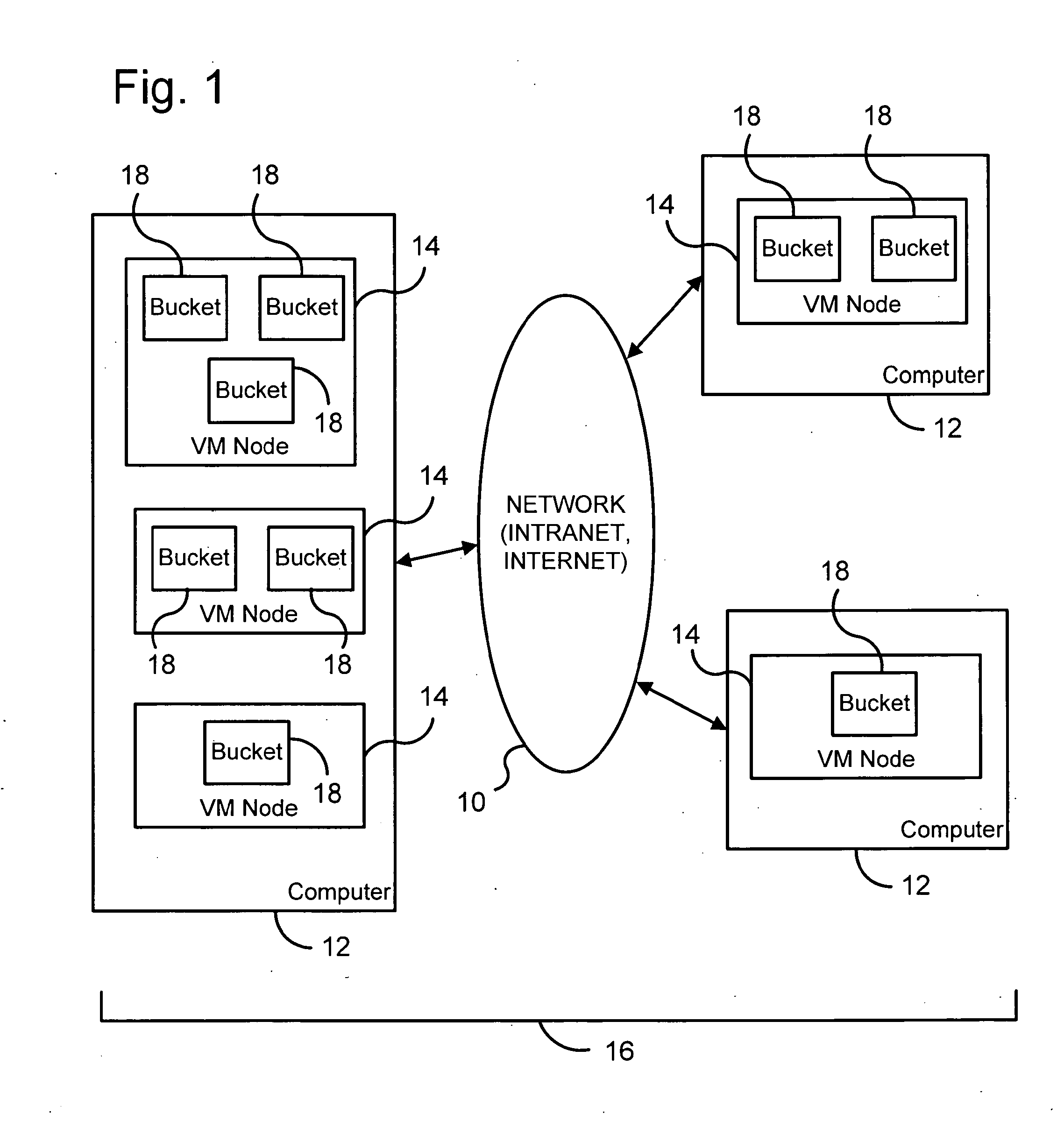
[0020]FIG. 1 is a block diagram illustrating a computer network 10 as an operating environment of the present invention. Computer network 10 includes multiple distinct computers 12 that are in network communication with each other. Each computer 12 operates at least one virtual machine (e.g., a Java virtual machine) as a node 14 of a distributed hash map data management system 16 of the present invention. Each virtual machine node 14 includes one or more logical stores or “buckets”18 into which data entries data objects are stored.

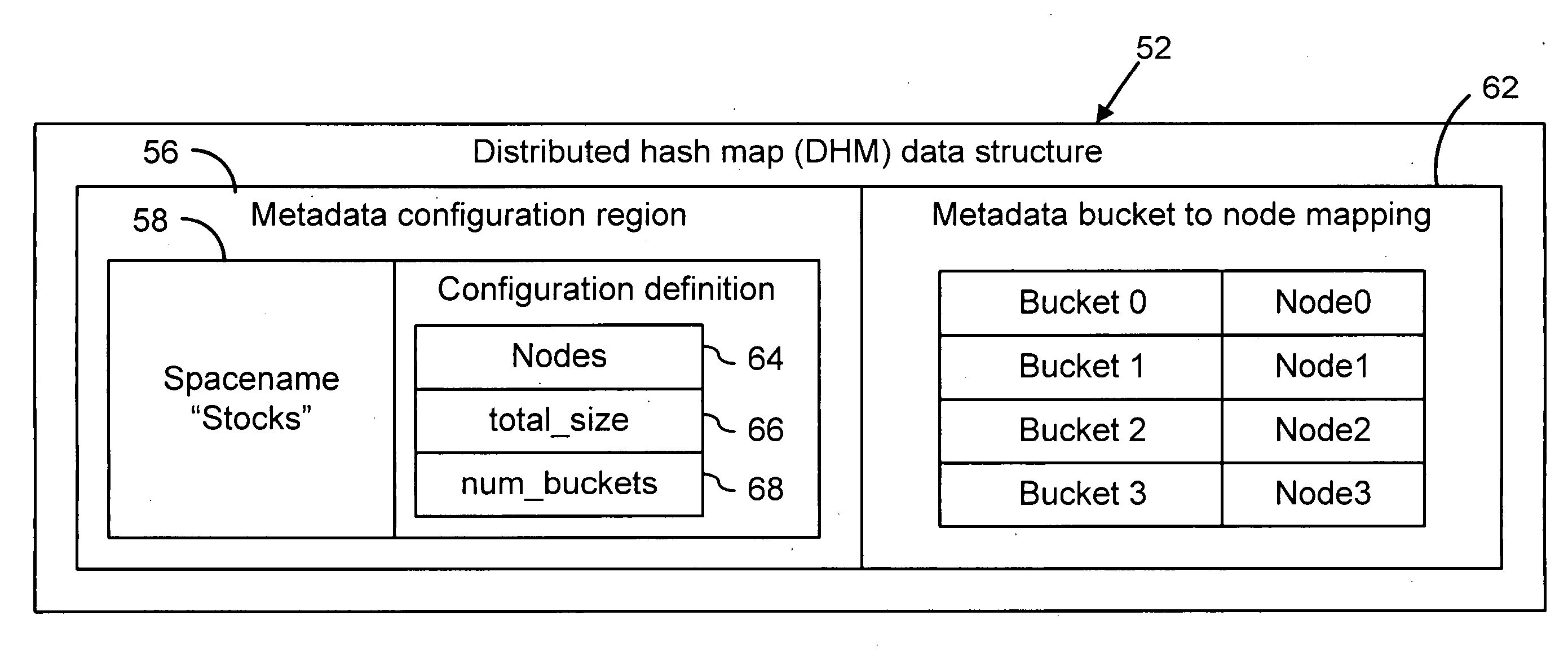
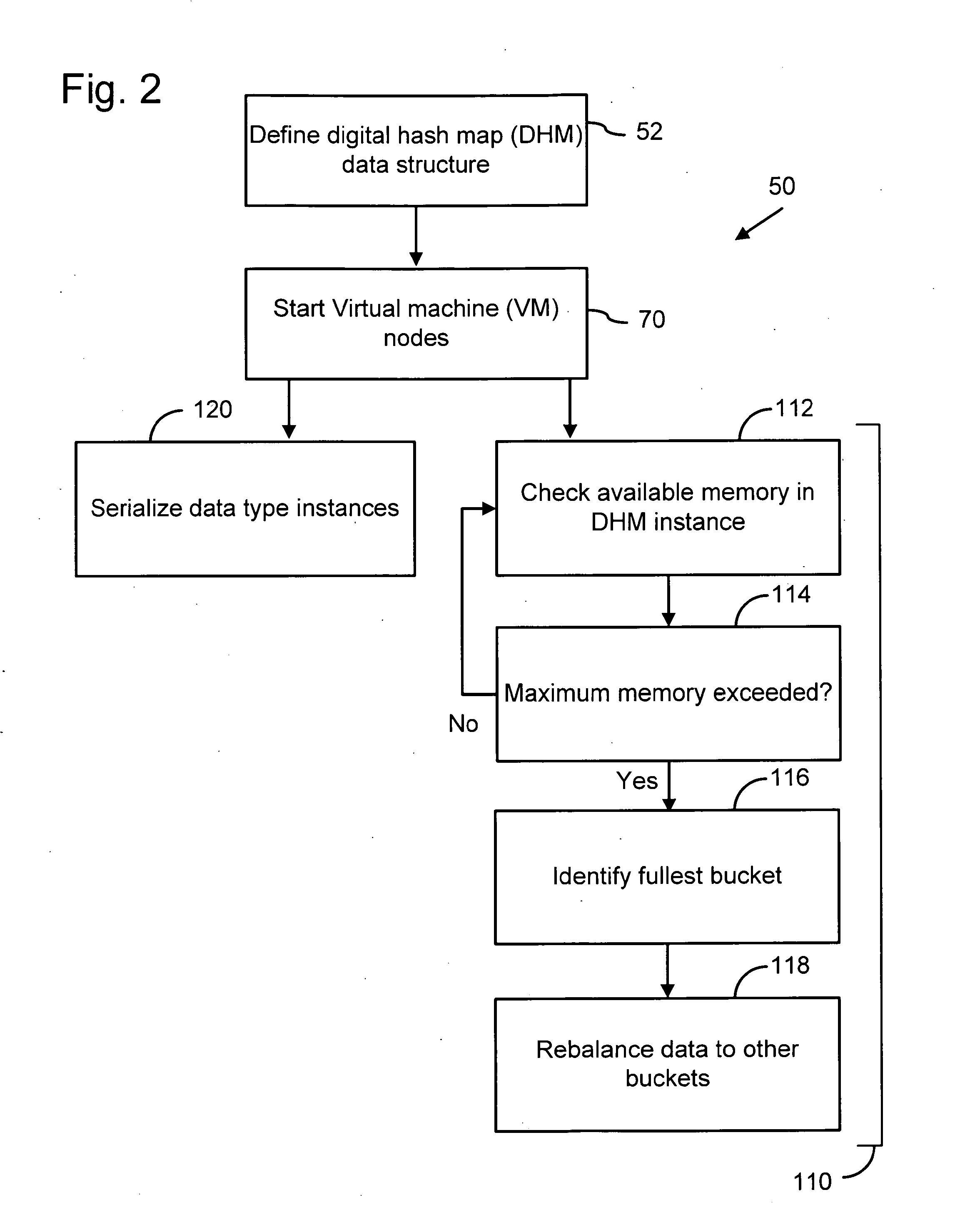
[0021]FIG. 2 is a flow diagram of a distributed data management method 50 that simultaneously provides highly scalable and highly concurrent distribution of data over multiple networked nodes 14. Distributed data management method 50 operating on computer network 10 is referred to as a distributed data management system 16 and is described with reference to a distributed hash map (DHM) data structure 52, which is illustrated in FIG. 3. Distributed hash map...


PUM


Abstract

A distributed data management system has multiple virtual machine nodes operating on multiple computers that are in communication with each other over a computer network. Each virtual machine node includes at least one data store or “bucket” for receiving data. A digital hash map data structure is stored in a computer readable medium of at least one of the multiple computers to configure the multiple virtual machine nodes and buckets to provide concurrent, non-blocking access to data in the buckets, the digital hash map data structure including a mapping between the virtual machine nodes and the buckets. The distributed data management system employing dynamic scalability in which one or more buckets from a virtual machine node reaching a memory capacity threshold are transferred to another virtual machine node that is below its memory capacity threshold.

Description

CROSS REFERENCE TO RELATED APPLICATIONS[0001]This application is a continuation of U.S. patent application Ser. No. 11 / 431,500 entitled “Distributed Data Management System” and filed May 9, 2006, which claims priority to U.S. provisional application 60 / 703,678 filed Jul. 28, 2005 and entitled “Distributed Data Management System,” both of which are hereby incorporated by reference.FIELD OF THE INVENTION[0002]The present invention to data management and, in particular, to managing data in a multicomputer environment to provide dynamic scalability while simultaneously providing concurrent, non-blocking access to data.BACKGROUND AND SUMMARY OF THE INVENTION[0003]In the field of data management, maximizing both scalability and performance at the same time is a challenging problem. Scalability and performance are often conflicting objectives because improvements in one typically come at the expense of the other. In a multicomputer environment, where processes are physically distributed, t...

Claims


Application Information

Patent Timeline
IPC IPC(8): G06F17/30
CPCG06F17/303G06F17/30G06F16/214G06F16/00
Inventor OKAMOTO, RUSSELL
Owner GOPIVOTAL
Learn More