
Single Pin Read-Write Method And Interface

a read-write and single-pin technology, applied in the field of serial transmission of data, can solve the problems of large amount of support circuitry, complicated protocol for such prior art serial interfaces, and large amount of documentation, and achieve the effect of simple implementation and low pin coun

Active Publication Date: 2011-08-04
ANALOG DEVICES INC
View PDF6 Cites 10 Cited by
  • Summary
  • Abstract
  • Description
  • Claims
  • Application Information

AI Technical Summary

Benefits of technology

One advantage of the present invention is that only a single pin is required. The same pin and net is used for clock, data, and communication in either direction. This permits lower pin counts on ICs that need a serial interface.
is that only a single pin is required. The same pin and net is used for clock, data, and communication in either direction. This permits lower pin counts on ICs that need a serial interface.
Another advantage is that the communication does not required RF encoding or a fixed baud rate to operate.
Yet another advantage is that the single pin system is simple to implement.
Yet still another advantage is that the single pin system can be used with any automatic test equipment, which is designed to be the master. Thus, the device under test need only implement the slave portion of the interface and implement the slave portion of the protocol.

Problems solved by technology

The protocol for such prior art serial interfaces is usually quite complex, requiring detailed documentation and a large amount of support circuitry.

Method used


Image

  • Single Pin Read-Write Method And Interface
  • Single Pin Read-Write Method And Interface
  • Single Pin Read-Write Method And Interface

Examples


Embodiment Construction

Voltage Only Method

The voltage signals have 3 (three) levels, say VDD, GND, and VDD / 2, but any three distinct levels can be used. Initially, the master drives the bus, and the slave has a high-impedance state.

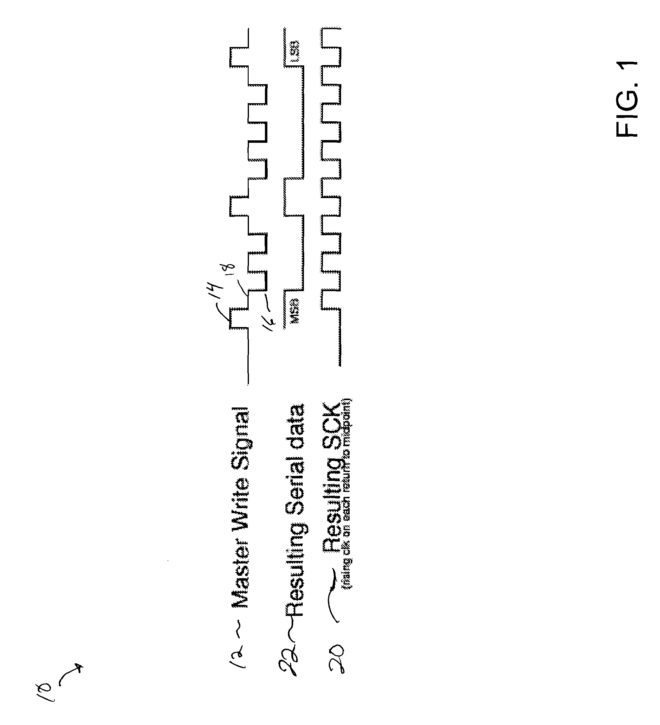
Referring to FIG. 1, the master controls the timing and initiates any activity. In the master write signal 12, the master writes to the slave by driving to VDD 14 for a “1”, and GND 16 for a “0”. Slaves remain in the high-impedance state and receive the data. The transition back to the midpoint 18 serves as the serial clock (SCK) 20. When the slave drives the serial interface, it controls the timing. Thus, for both the master and the slave, the serial data 22 is VDD (1) or GND (0) and the transition to VDD / 2 indicates a clock 20.

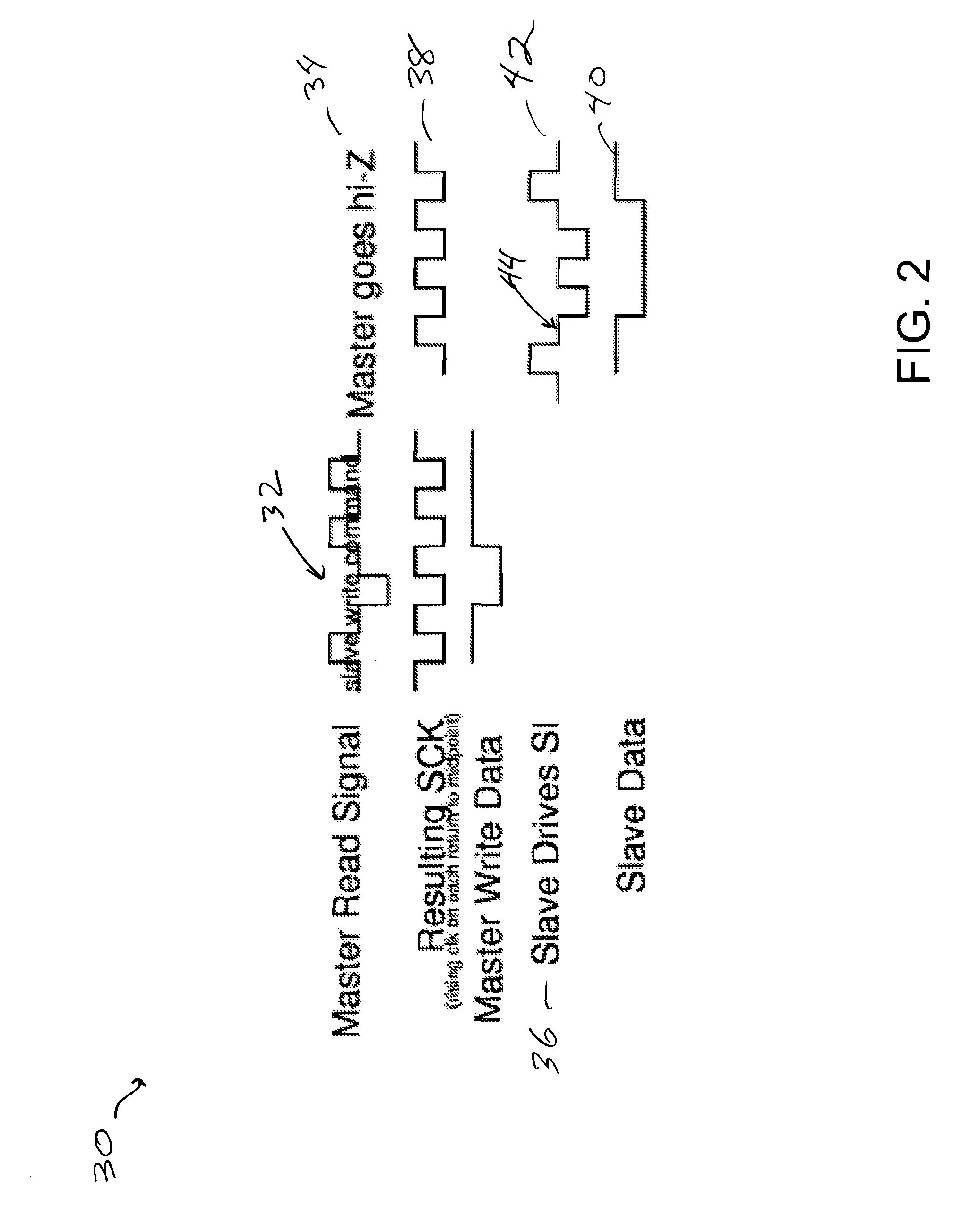
As shown in FIG. 2, when commanded by the master, the slave drives the bus and the master assumes a high-impedance state. In FIG. 2, the master goes the high-impedance state 34 after it sends the slave write command 32 in anticipation of the slave contr...


PUM


Abstract

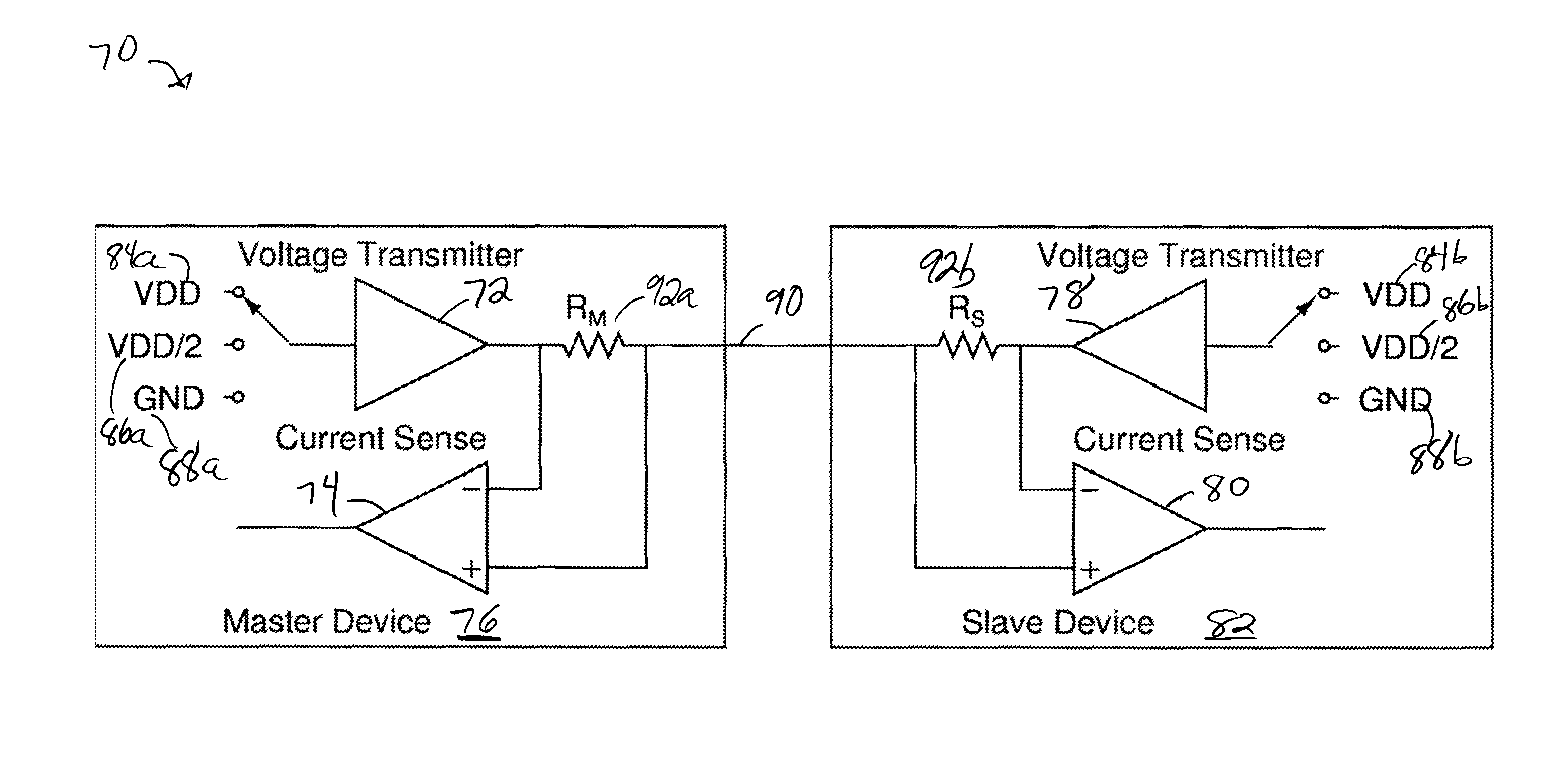
A method of communicating on a single serial line between two devices is disclosed. The method includes combining a data stream and a clock to form a three-voltage level stream such that the third voltage level records the transitions of the clock while the serial data is either high or low. Either the first or the second device can send a combined stream on the line. The method further includes, in some embodiments, the second device driving the same voltage levels as those transmitted by the first device and the first device sensing current on the single serial line to determine that the second device has received data from the first device.

Description

FIELD OF THE INVENTIONThe present invention generally relates to serial transmission of data between devices and more particularly to a serial transmission using a single connection between a pair of devices.DESCRIPTION OF THE RELATED ARTPrior art serial interfaces typically use two pins, one for clock and one for data or one for transmitted data and one for received data. Additionally, prior art interfaces usually have a fixed baud rate or RF encoding. The protocol for such prior art serial interfaces is usually quite complex, requiring detailed documentation and a large amount of support circuitry. There is a need for a much more simple serial interface.BRIEF SUMMARY OF THE INVENTIONThe present invention provides a simpler serial interface. At the physical level, it uses a single pin. Clock and data bits are encoded on a single net connected to the pin. In a first method, voltage only communication is used. In a second method, both voltage and current are used. At the protocol lev...

Claims


Application Information

Patent Timeline
Patent Type & Authority Applications(United States)
IPC IPC(8): G06F13/00G06F1/06
CPCG06F1/06G06F13/00G06F13/4291H04L7/0008
Inventor BECCUE, STEPHEN MARK
Owner ANALOG DEVICES INC
Learn More