
Storage controller and virtual volume control method

Active Publication Date: 2011-08-04
HITACHI LTD
View PDF13 Cites 46 Cited by
  • Summary
  • Abstract
  • Description
  • Claims
  • Application Information

AI Technical Summary

Benefits of technology

[0012]That is, in a case where it is supposed that the technology disclosed in the above-mentioned Literature has been applied to a storage controller that configures a RAID group in physical disk drive units, a physical area would have to be managed using a plurality of different management methods, making the configuration complex and increasing development costs as well.
[0015]Accordingly, an object of the present invention is to provide a storage controller and a virtual volume control method that make it possible to efficiently associate a storage area to a virtual volume taking into account the physical configuration of the RAID group. Another object of the present invention is to provide a storage controller and a virtual volume control method that make it possible to configure a virtual volume by making uniform use of the respective RAID groups. Yet another object of the present invention is to provide a storage controller and a virtual volume control method that make it possible to efficiently associate a storage area with a virtual volume, and, in addition, make it possible to improve the response performance of the virtual volume. Yet other objects of the present invention should become clear from the disclosure of the embodiments described below.Solution to Problem

Problems solved by technology

The amount of data being used by users is increasing on a daily basis, and volume sizes established to meet the situation as it stands now do not provide enough capacity.
By contrast, in cases where the volume size is set larger than the size currently required in anticipation of increases in data, many nonessential disk drives result, raising costs.

Method used


Image

  • Storage controller and virtual volume control method
  • Storage controller and virtual volume control method
  • Storage controller and virtual volume control method

Examples


example 1

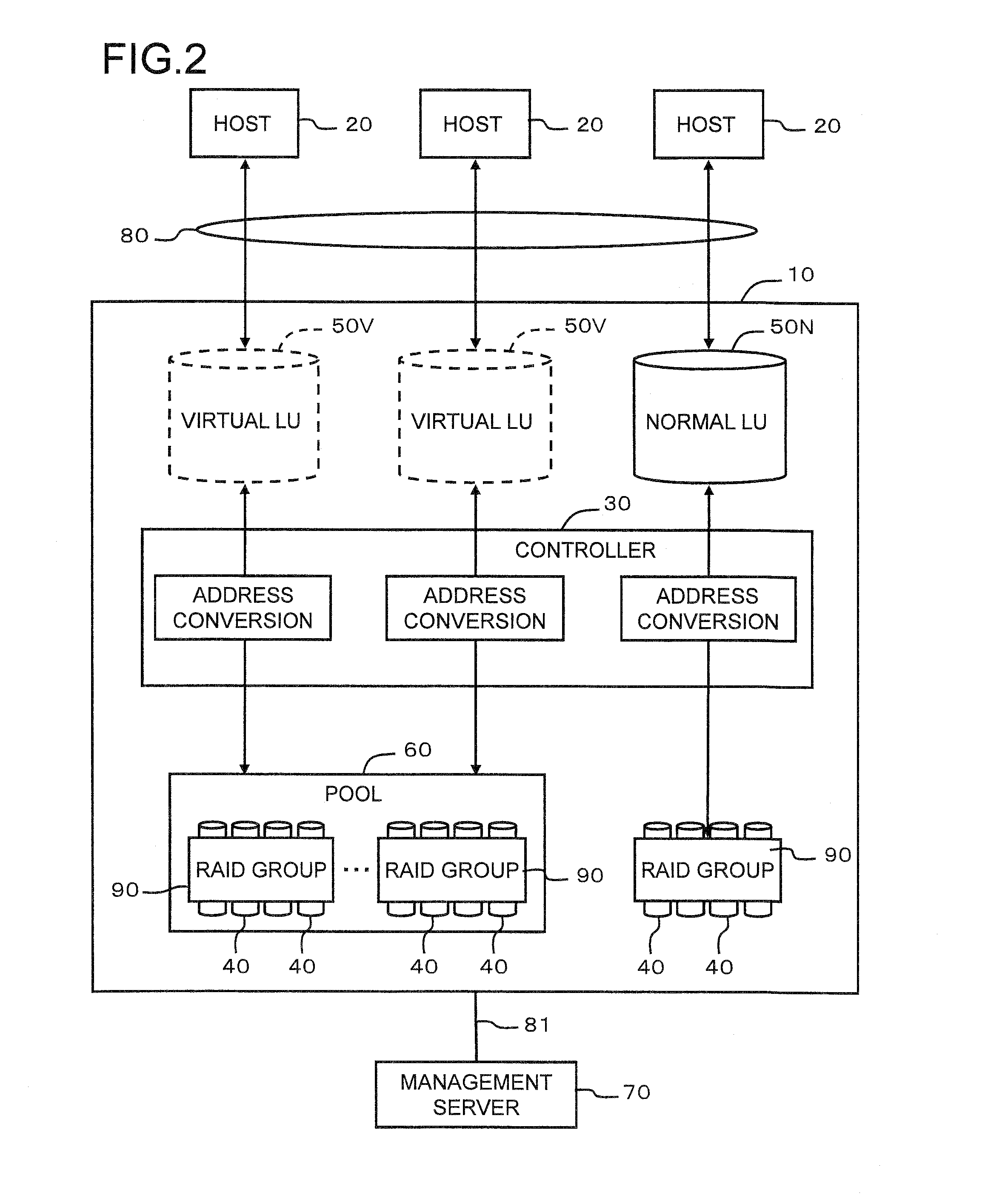
[0087]FIG. 2 is a schematic diagram showing the overall configuration of an information processing system comprising a storage controller 10 related to this embodiment. This information processing system, for example, is able to comprise at least one storage controller 10, either one or a plurality of hosts 20, and at least one management server 70.

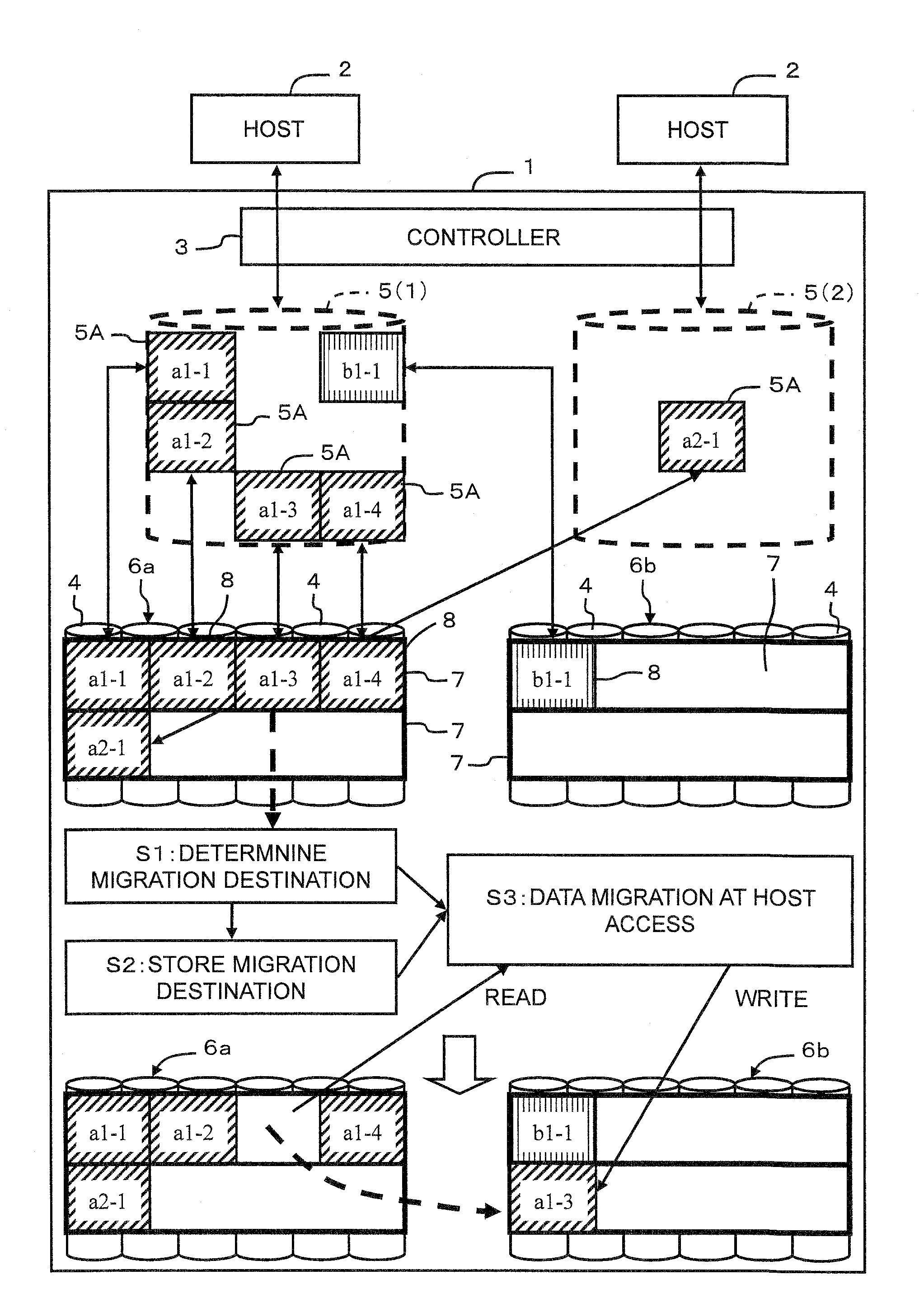
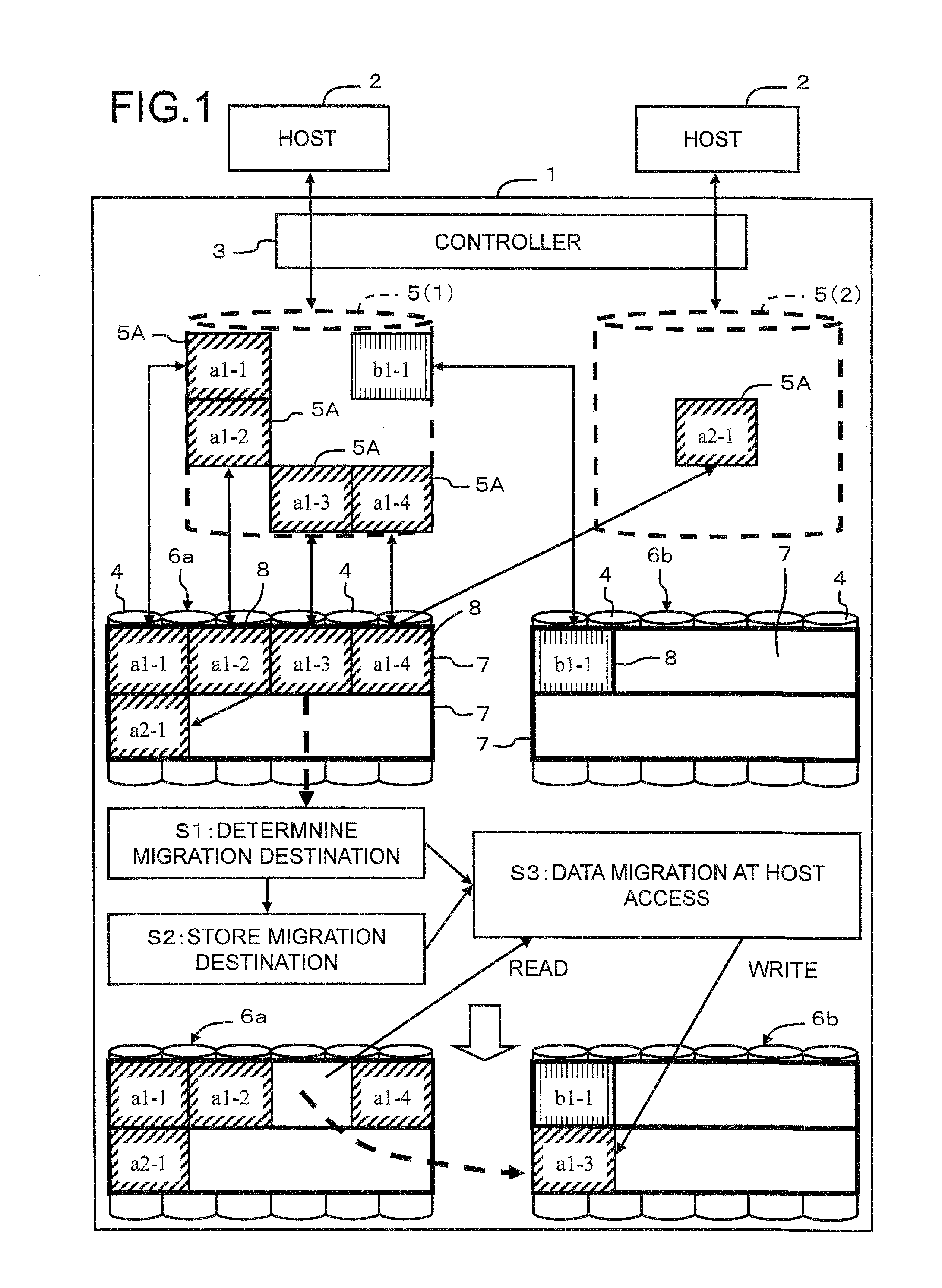
[0088]The corresponding relationship with the embodiment described above in FIG. 1 will be explained. The storage controller 10 corresponds to the storage controller 1, the host 20 corresponds to the host 2, the controller 30 corresponds to the controller 3, the storage device 40 corresponds to the storage device 4, the virtual volume 50V corresponds to the virtual volume 5, and the RAID group 90 corresponds to the RAID groups 6a, 6b. As much as possible, explanations that duplicate the explanation given for FIG. 1 will be omitted.

[0089]The host 20 and the storage controller 10 are connected via a first communication network 80. The first...

example 2

[0250]A second embodiment will be explained on the basis of FIGS. 31 and 32. This embodiment corresponds to a variation of the first embodiment. Therefore, the explanation will focus on the differences with the first embodiment. When creating the data migration plan, this embodiment frees the real page 92 on which only the NULL data is stored from the virtual volume 50V and returns same to an unused page.

[0251]FIG. 31 is a flowchart showing a migration destination determination process according to this embodiment. Compared to the flowchart shown in FIG. 27, this flowchart also comprises a process (S210) for deleting the zero-data (NULL data). In the migration destination determination process, the controller 30 first returns the real page 92 storing only zero-data to an unused page, and thereafter, executes the load distribution process and the utilization capacity leveling process.

[0252]FIG. 32 is a flowchart of the zero-data deletion process. The controller 30 carries out the fol...


PUM


Abstract

A storage controller allocates a real storage area to a virtual volume in chunk units each comprising a plurality of pages. In a case where load bias occurs between RAID groups, data reallocation is carried out. A real storage area inside a pool is allocated to a virtual volume 5 in accordance with a write access. A RAID group 6 comprises a plurality of chunks. Each chunk 7 comprises a plurality of pages 8. The pages 8, from within the chunk 7 that has been allocated to the virtual volume 5, are used. A data migration plan is created and stored in page units based on the load of each RAID group. When a host 2 issues a command to a migration-targeted page, data is migrated while this command is being processed.

Description

TECHNICAL FIELD[0001]The present invention relates to a storage controller and a virtual volume control method.BACKGROUND ART[0002]Users, such as companies and the like, utilize storage controllers to manage data. The storage controller forms a logical volume on a storage area on the basis of RAID (Redundant Array of Independent Disks). This logical volume is provided to a host computer (hereinafter, host).[0003]The amount of data being used by users is increasing on a daily basis, and volume sizes established to meet the situation as it stands now do not provide enough capacity. By contrast, in cases where the volume size is set larger than the size currently required in anticipation of increases in data, many nonessential disk drives result, raising costs.[0004]Accordingly, technologies for preparing a virtual logical volume and allocating a real storage area to the virtual logical volume in accordance with actual use have been proposed (Patent Literature 1 and Patent Literature 2...

Claims


Application Information

Patent Timeline
IPC IPC(8): G06F12/02
CPCG06F3/0605G06F3/061G06F3/0644G06F11/1076G06F3/0665G06F3/067G06F11/1008G06F3/0647
Inventor KAWAGUCHI, YUTAROISHIKAWA, ATSUSHIUCHIUMI, KATSUHIRO
Owner HITACHI LTD
Learn More