
Image processing system

Active Publication Date: 2009-05-21
BAUMER OPTRONIC
View PDF10 Cites 8 Cited by
  • Summary
  • Abstract
  • Description
  • Claims
  • Application Information

AI Technical Summary

Benefits of technology

[0018]One object of the present invention is therefore to provide an image processing system which ensures high resolution with fast processing at the same time, in order in particular to allow processing in video real time.
[0019]A further object of the invention is to provide an image processing system which ensures reliable identification of the image information, in particular reliable and low-error edge detection and segmentation, as well as efficient object association and efficient compression of the image information.
[0020]Another object of the invention is to provide an image processing system which is cost-effective, and which in particular can be manufactured in series production.

Problems solved by technology

Since the codes are relatively small in comparison to the cars, and can be applied at different points, this application is extremely demanding with respect to the required quality and resolution.
However, the different illumination in a production line also results in considerable difficulties for image identification.
This is associated with ever more stringent demands for the processing speed.
These basic structures are in the simplest case straight lines or curved lines, although they may also be of a more complex nature.
Evaluation of the gradient magnitude just by a threshold value comparison is disadvantageous in particular because the edge location is heavily influenced by noise and the local illumination level.
The contact points that are found must be postprocessed in a complex form, and the processes which are required for this purpose considerably restrict the scope for a real-time capability.
Furthermore, in this method, the resolution is restricted by the image matrix, so that the resolution is inadequate for many fields of application.
On the other hand, major refinements of the image matrix in order to increase the resolution cannot be carried out indefinitely, either, since the processing time would otherwise explode.
The described method is therefore disadvantageous and, in particular, is barely suitable for use in the demanding exemplary embodiment described above in the field of motor vehicle production.
However, many other applications, such as precise edge measurements, can also be carried out only to a restricted extent in this way.
However, these methods are generally software based and are therefore generally too slow in order to carry out processing in video real time with appropriately high resolution.
Furthermore, subsystems such as these are unreasonably complex.
In addition, the processes that are used cannot be transferred directly to hardware solutions.

Method used


Image

  • Image processing system
  • Image processing system
  • Image processing system

Examples


Embodiment Construction

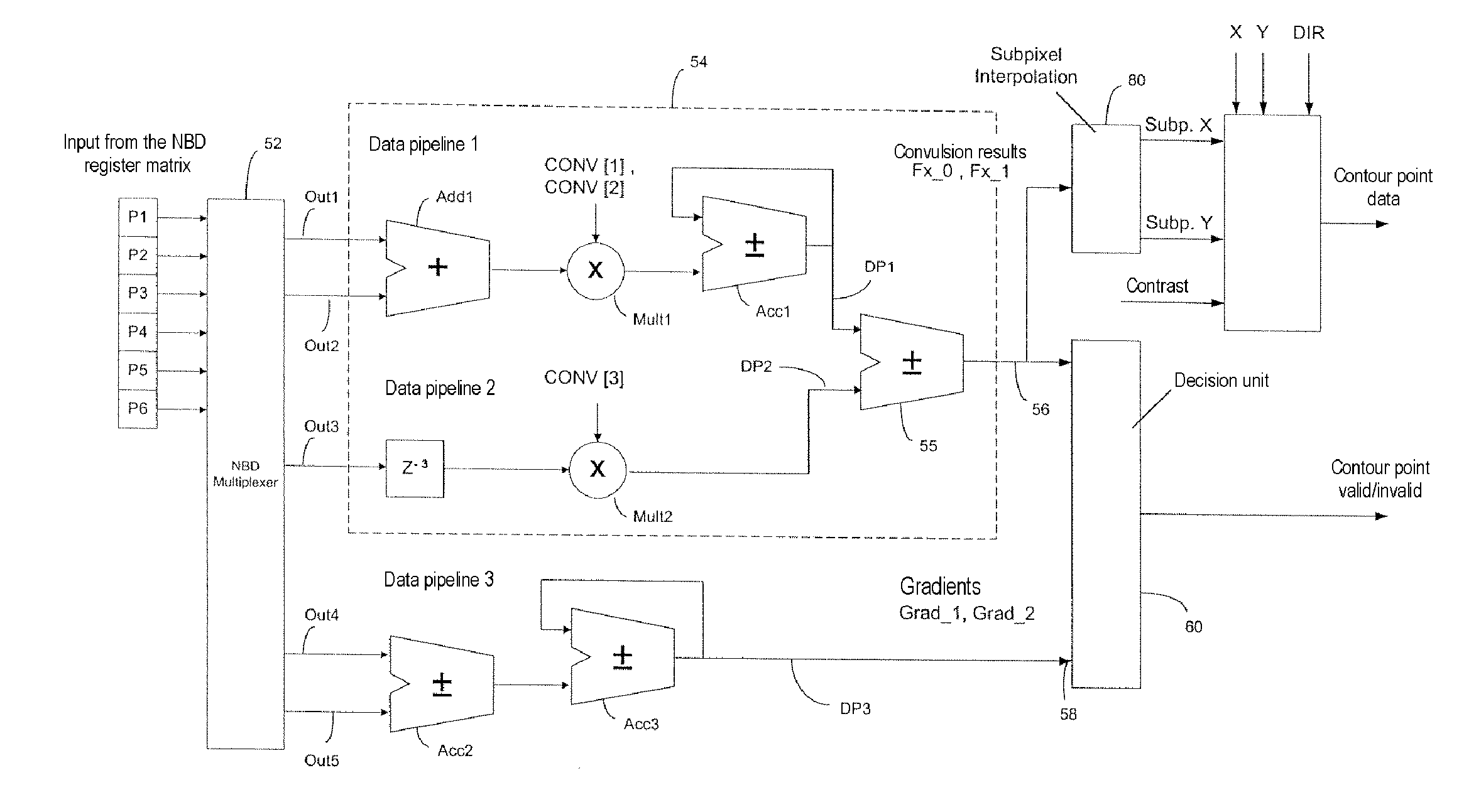
[0084]The omnidirectional image processing system 1 (FIG. 11) according to the invention, or the code reader, comprises an imaging system 2, an analog / digital converter 4, a digital processing device 6, a computation device 8, a microcomputer which is not shown, and an optional illumination device 9 (FIG. 23).

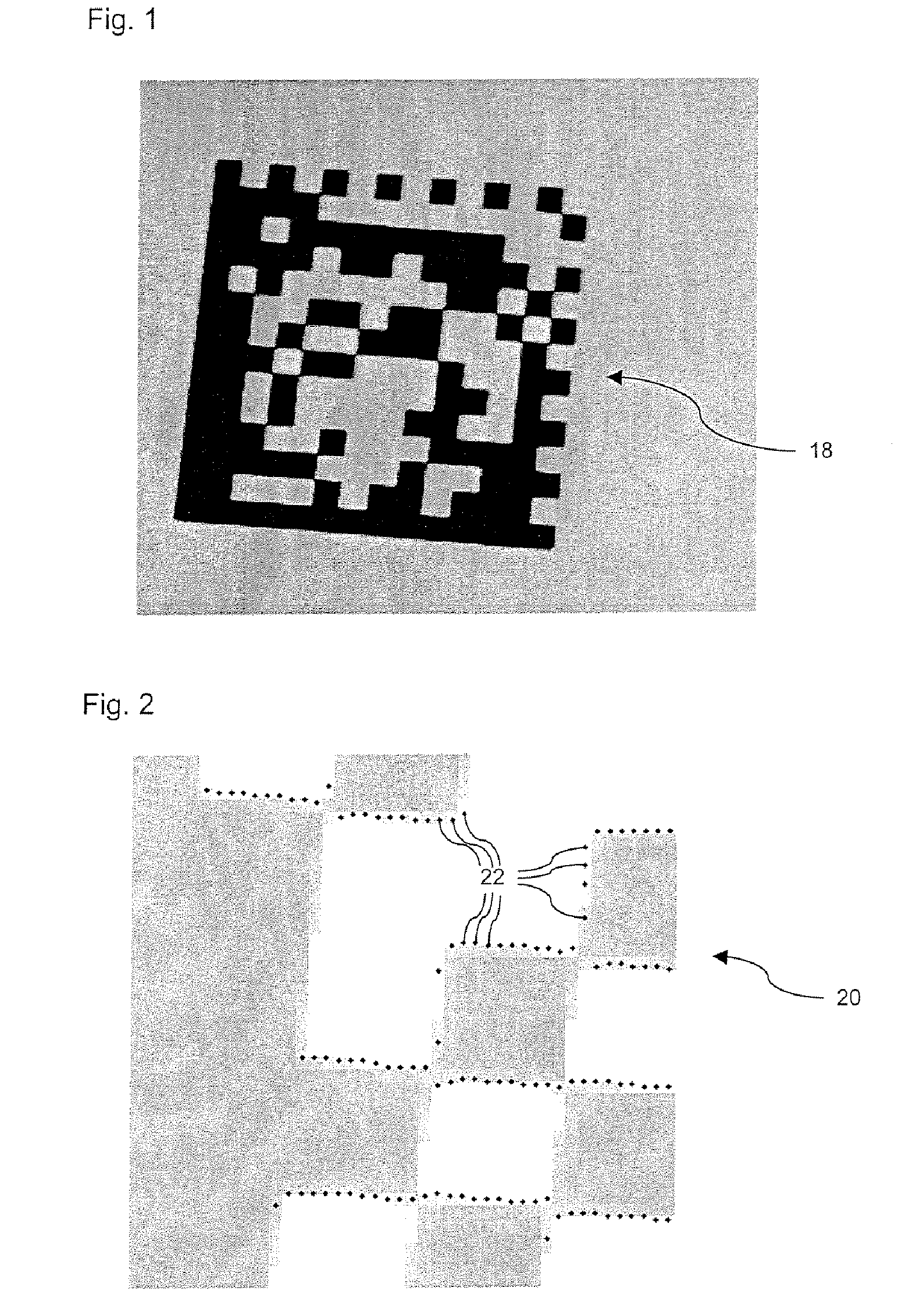
[0085]In the following exemplary embodiment described in detail, the operation will be explained on the basis of a digital CCD matrix camera 10. This camera 10 represents an exemplary embodiment of the imaging system 2 and of the analog / digital converter 4 and produces digital image data, in the form of a digital image datastream 12 continuously or on a triggered basis. However, the imaging system 2 may also be a scanner, a CT scanner or the like, for example even an arrangement of a plurality of imaging systems. The image data is shown in the form of gray-scale image in a two-dimensional illustration in FIG. 1. Based on this example, FIG. 1 shows a slightly rotated data matrix...


PUM


Abstract

The invention relates to an image processing system for omnidirectional reading of optical patterns, for example of one-dimensional and two-dimensional codes.One object is to provide an image processing system which ensures high resolution with rapid processing at the same time in order, in particular, to allow processing in video real time and to provide reliable identification of the image information, in particular reliable and low-error edge detection, segmentation and object association.According to the invention, this is achieved by the use of a plurality of convolvers, which operate in parallel and / or using the time-division multiplexing method, for convolution of the digital image data, of a neighborhood processor (90) for reading and linking contour points (22), and / or of a statistical processor for reading a segment list.

Description

FIELD OF THE INVENTION[0001]The invention relates to an image processing system in general, and to an image processing system for omnidirectional reading of optical patterns, for example of one-dimensional and two-dimensional codes, in particular.BACKGROUND OF THE INVENTION[0002]Image processing for automatic pattern recognition is currently one of the most demanding and excellent research fields. The potential applications are virtually unlimited.[0003]Simple precursors of pattern recognition are the widely used laser scanner for detection of one-dimensional barcodes. However, digital image processing goes well beyond this since it can be used not only to identify one-dimensional barcodes, but also two-dimensional codes or complex images, in particular and in addition the structure which is unknown from the start as far as identification of how this is also made possible by the eye in conjunction with the brain.[0004]One possible application, for example, is the identification of a...

Claims


Application Information

Patent Timeline
IPC IPC(8): G06K9/64G06T5/00G06T5/20
CPCG06T5/20G06T7/0083G06T2200/28G06T2207/30248G06T2207/10081G06T2207/30208G06T2207/10016G06T7/12
Inventor BEIKIRCH, LARSFEDORENKO, SERGEJSCHWARZ, DITTMARIHLEFELD, JOACHIMWENERT, LUTZ
Owner BAUMER OPTRONIC
Learn More