
Culture apparatus

a technology of culture apparatus and piping, which is applied in the field of culture apparatus, can solve the problems of troublesome work to load or unload from the shelf for harvesting, complicated piping paths, etc., and achieve the effect of simple shelf and container configuration, easy planting of seeds, and low height of culture apparatus

Inactive Publication Date: 2011-08-11
UCHIYAMA HISAKAZU
View PDF5 Cites 70 Cited by
  • Summary
  • Abstract
  • Description
  • Claims
  • Application Information

AI Technical Summary

Benefits of technology

[0005]The present invention is directed to make an air supply path simple without impairing the merit of the cultivating shelf of Paten Document 2.Further, the present invention is directed to provide a culture apparatus which can perform efficiently the loading and unloading of containers for cultivation.Further, the present invention is directed to provide a culture apparatus which can cultivate easily a small plant.
[0032]Further, in the case that the blocking wall is equipped with thermal insulation property (claim 21), energy saving effect is further high. Further, in the case that the container is housed in the space surrounded by the blocking wall so as to be retrievable freely (claim 22), planting, harvesting of plants is easy. A shifting apparatus to shift the container within a space surrounded by the blocking wall is further provided (claim 23), since the container shifts in the culture apparatus, seedlings of plants are let in from an inlet port and is made to shift to an outlet port, it is possible to take out the plants grown in the period being shifted.

Problems solved by technology

However, since the cultivating floor serving as a cultivating unit is long, the work to load on a shelf or to unload from the shelf for harvesting is troublesome.
However, since in order to send in air air-conditioned by an air conditioner, it becomes necessary to provide an individual air supply pipe, and to pass the air supply pipe through interior of the support, piping paths become complicated.

Method used


Image

  • Culture apparatus
  • Culture apparatus
  • Culture apparatus

Examples


Embodiment Construction

[0057]Hereinafter, the embodiments of the present invention will be described referencing the drawings.

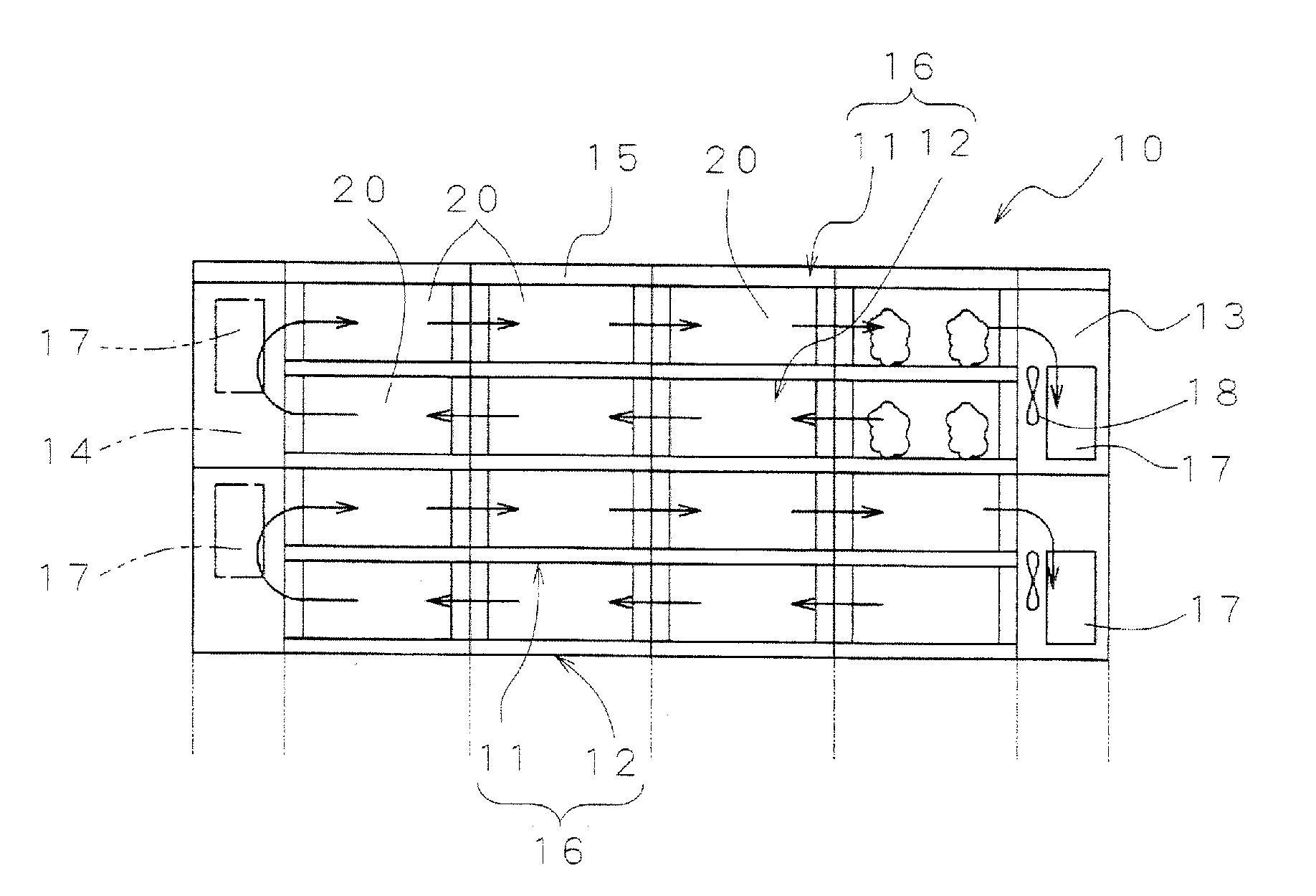
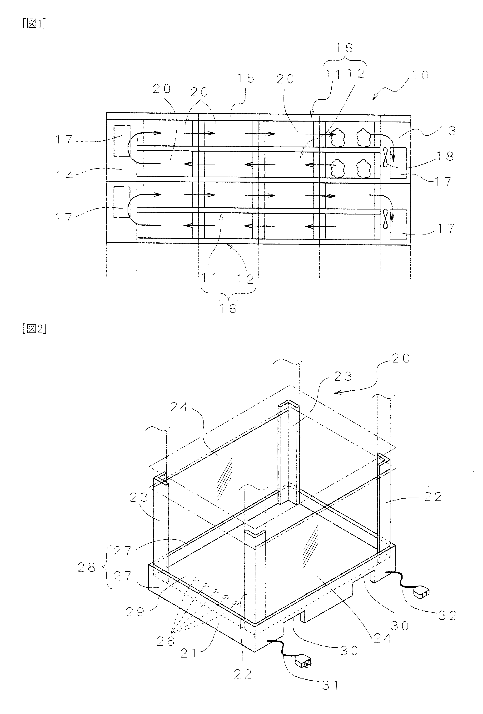
[0058]A culture apparatus 10 shown in FIG. 10 is made to be a cultivating shelf including rows 11, 12 of a cultivating unit 20 stacked above and below in a plurality of stages, an air conditioning chamber 13 arranged in one end portion of these rows 11, 12, a turnaround chamber 14 or a turnaround duct arranged in another end portion, and a cover 15 covering the upper plane of the upper most row 12. In this embodiment, the upper row 11 and the lower row 12 are made to be one set of upper and lower two stages, by every set 16, the air conditioning chamber 13 and the turnaround chamber 14 are divided. In the air conditioning chamber 13, the heat exchanger (air conditioner) 17 is arranged, the air of which the temperature and the component are suitably controlled is sent to the right end of the cultivating unit 20. As the control of the component, the contained amount of carbon dioxide...


PUM


Abstract

[Problem to be Solved]To simplify an air supply path without damaging the merit of conventional culture apparatus.[Solution]A culture apparatus 10 includes a row 11 of a plurality of box-shaped containers 21 for plant cultivation, and a row 12 of lower stage containers 21 arranged in the lower portion of the row 11, holding the upper stage container 21 spaced as high as the height after growth of the plants to be cultivated. In each container 21, a support 22, a blocking film 24 stretched between front and rear, right and left supports of the container 21 are provided. In the one end of the rows 11, 12 of the containers 21, an air conditioner 17 is arranged, in another end, a turnaround chamber 14 is provided.

Description

FIELD OF THE INVENTION[0001]This invention relates to a culture apparatus, for more details, to a culture apparatus which is suitable for industrial cultivation such as hydroponic cultivation etc., and can save an installation space.DESCRIPTION OF BACKGROUND ART[0002]The applicant has proposed previously a shelf including a plurality of stick shelf members, and a cultivation shelf including a plurality of slender cultivating floors laid slidably on the shelf in a direction intersecting the shelf member (refer to Patent Document 1). In the Patent Publication, it is further described that a heat insulation material and a heat radiating pipe are provided in the cultivating floor, and that a transparent wall made of synthetic resin for preventing a convection flow is also provided, which partitions the upper space of the cultivating floor from a surrounding area (refer to FIG. 1 of the Patent Publication).[0003]Further, the applicant has disclosed a cultivating shelf of stacking method,...

Claims


Application Information

Patent Timeline
IPC IPC(8): A01G9/24A01G9/02
CPCA01G31/06A01G9/24Y02A40/25Y02P60/21
Inventor UCHIYAMA, HISAKAZU
Owner UCHIYAMA HISAKAZU
Learn More