Cooling structure, electronic device using same, and cooling method

a cooling structure and electronic device technology, applied in the direction of lighting and heating apparatus, basic electric elements, semiconductor devices, etc., can solve the problems of insufficient cooling efficiency, insufficient space for mounting a cooling unit having a sufficient size, and insufficient cooling of lsi circuits and/or ics which generate a large amount of heat, etc., to achieve smooth flow, avoid cooling capacity drop, and effectively be in contact with the boiling surface

Active Publication Date: 2011-08-11
NEC CORP
View PDF25 Cites 39 Cited by
  • Summary
  • Abstract
  • Description
  • Claims
  • Application Information

AI Technical Summary

Benefits of technology

[0025]According to a cooling structure of the present invention, a liquid phase coolant, without staying between a vapor port and liquid return port, flows into an evaporation chamber from the liquid return port and flows toward a direction of the vapor port located on a side opposite to the liquid return port in a manner to trace a boiling surface in the evaporation chamber. Therefore, bubbles in a vapor phase state produced by evaporation caused by contact of the liquid phase coolant with the boiling surface are immediately moved (taken away) by flowing load of the liquid phase coolant flowing in parallel to the boiling surface and are allowed to rise by buoyancy of bubbles themselves. The vapor ph

Problems solved by technology

High speed signal transfer seems to be advantageously realized by shortening wiring length, however, the shortening of the wiring length makes it difficult to ensure space for mounting a cooling unit having a sufficient size corresponding to the amount of heat generated therein.
However, cooling efficiency of the cooling structures described in the Related Art Patent References 1 to 3 is not enough to cool an LSI circuit

Method used


Image

  • Cooling structure, electronic device using same, and cooling method
  • Cooling structure, electronic device using same, and cooling method
  • Cooling structure, electronic device using same, and cooling method

Examples


first exemplary embodiment

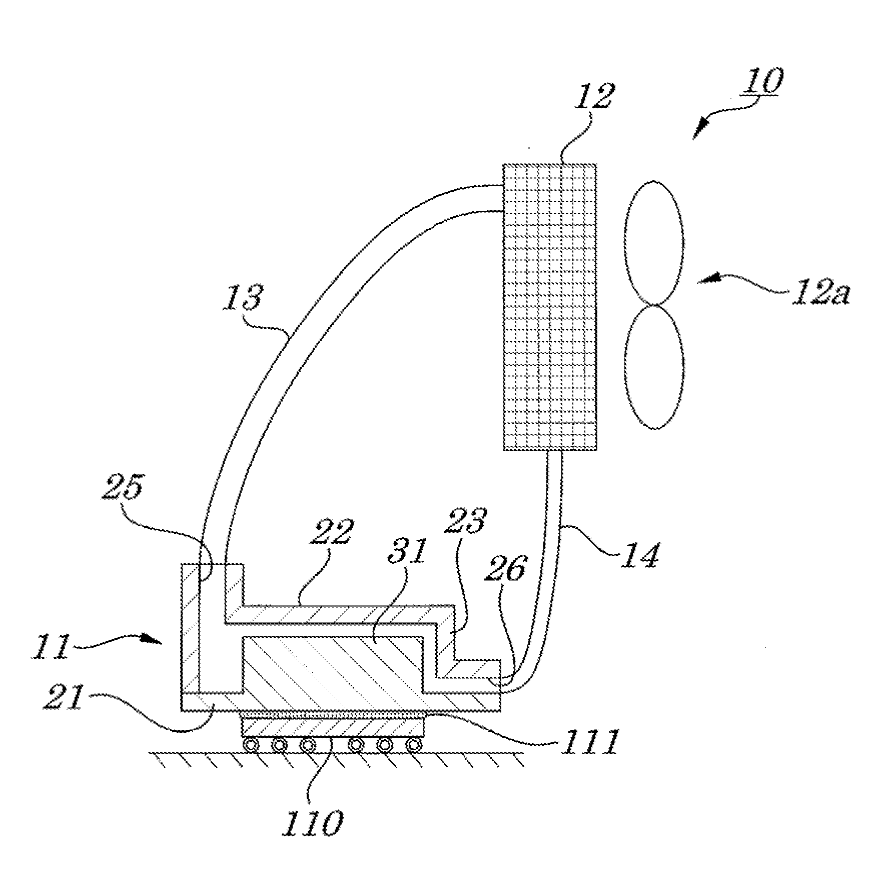
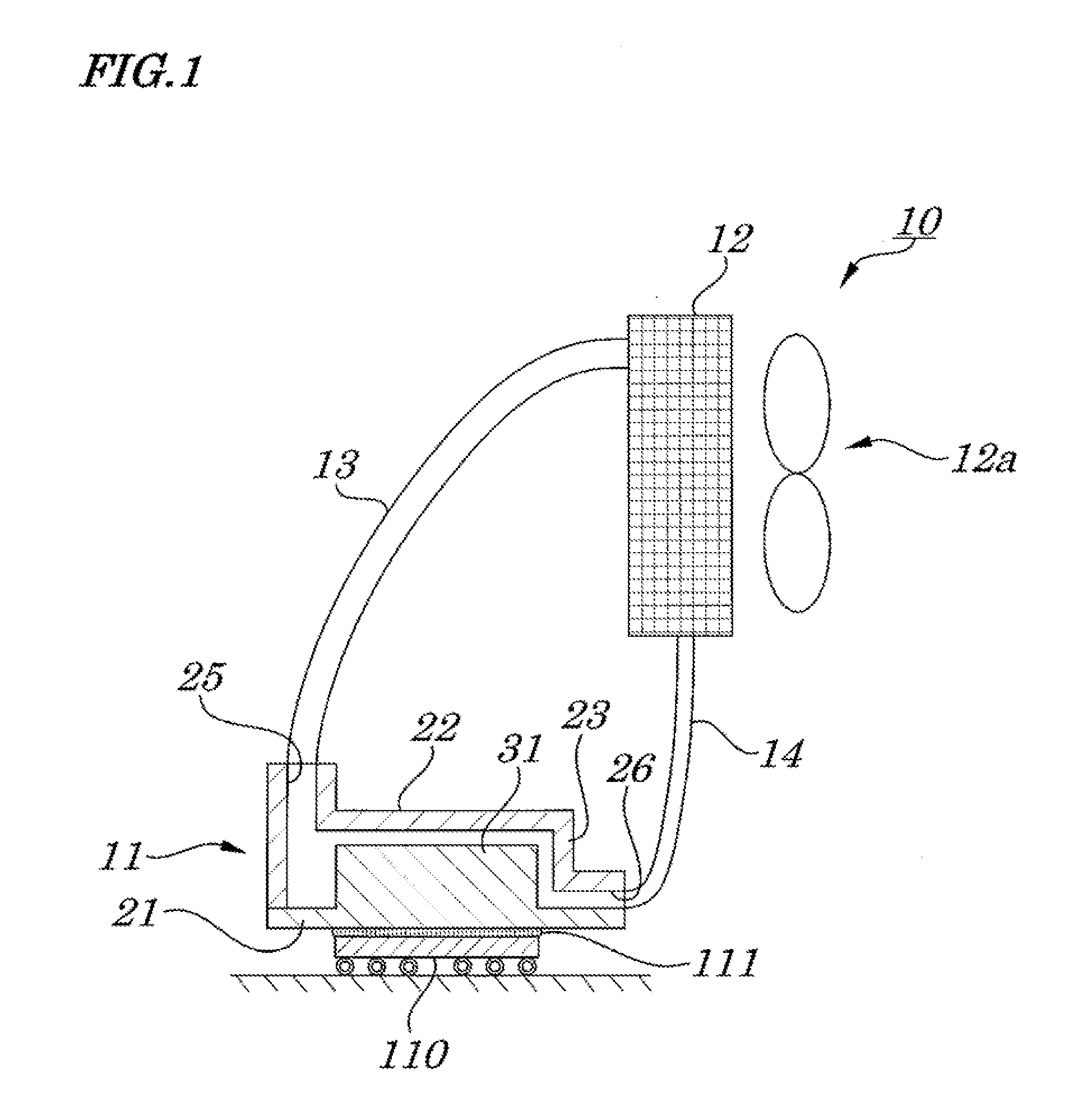
[0040]FIGS. 1 to 5 are diagrams showing a cooling structure according to a first exemplary embodiment of the present invention. FIG. 1 is a conceptual diagram showing diagrammatically an entire configuration of a cooling unit having the cooling structure. FIG. 2 is a perspective diagram of a vertical cross section showing an internal structure of an evaporation chamber of the cooling unit. FIG. 3 is a vertical cross-sectional view showing an internal structure of the evaporation chamber. FIG. 4 is a perspective view showing a structure of a boiling surface in the cooling unit. FIG. 5 is a vertical cross-sectional view showing a structure of plate-shaped fins on the boiling surface in the cooling unit. Here, each component of the cooling unit is shown in the drawings so that an up-and-down direction of its actual posture coincides with an up-and-down direction of each component shown in each drawing.

[0041]As shown in FIG. 1, the cooling unit 10 is attached onto an LSI package 110 (co...

second exemplary embodiment

[0055]FIG. 6 is a diagram showing a cooling structure according to a second exemplary embodiment of the present invention. That is, FIG. 6 is a vertical cross-sectional view showing an internal structure of an evaporation chamber in a cooling unit employing the above cooling structure. In the second exemplary embodiment, the cooling structure is approximately the same as for the first exemplary embodiment and, therefore, features of the invention are described by assigning same reference numbers to components having the same configuration. (The same applies to other exemplary embodiments described below.)

[0056]As shown in FIG. 6, an evaporation chamber 41 of a cooling unit 10 is mounted, through a heat transfer layer 111, on an LSI package 110, in a manner in which its boiling surface 21a of a base plate 21 is in a vertical posture. A cylindrical plate 23 is hermetically mounted, in a fixed manner, on a circumferential edge of each of the base plate 21 and a ceiling plate 22 of the ...

third exemplary embodiment

[0062]FIG. 7 is a diagram showing a structure for cooling according to a third exemplary embodiment of the present invention. That is, FIG. 7 is a vertical cross-sectional view showing an internal structure of an evaporation chamber in a cooling unit employing the above structure for cooling.

[0063]As shown in FIG. 7, in an evaporation chamber 51 of a cooling unit 10, as in the above second exemplary embodiment, a base plate 21 and ceiling plate 22 are mounted in a manner to be vertical to an LSI package 110. On a circumferential edge of each of the base plate 21 and ceiling plate 22, instead of the cylindrical plate 23 employed in the second exemplary embodiment, a cylindrical plate 53 is mounted hermetically in a fixed manner so as to have a same height as a plate-shaped fin 31.

[0064]A vapor port 55 to be connected to a vapor pipe 13 has, instead of the vapor port 45 in the above second exemplary embodiment and as in the case of the liquid return port 26, its aperture through the c...


PUM


Abstract

A maintenance-free cooling structure is provided which, by removing bubbles produced on a boiling surface utilizing an action other than buoyancy, heat change (heat transfer) is effectively brought about on the boiling surface, thus enabling efficient cooling and its miniaturization and low power consumption. The cooling structure has an evaporation chamber 11 connected through a vapor pipe and a liquid return pipe to a condensation chamber to allow a phase change to occur from a vapor phase coolant V to a liquid phase coolant L. In the evaporation chamber, as a result of contact of the liquid phase coolant L with the boiling surface of a base plate 21 and/or with plate-shaped fins, the phase change occurs from liquid to vapor. The evaporation chamber has an aperture operating as a vapor port 25 for the vapor pipe which is formed in a neighboring position along an inner circumferential surface 23a of a cylindrical plate 23 in a ceiling surface 22a and an aperture operating as a liquid return port for the liquid return pipe which is formed in a position neighboring to an end edge along the boiling surface on an inner circumferential surface on a side opposite to the vapor port 25, so that the flow-in direction of the liquid phase coolant is in parallel to the boiling surface.

Description

TECHNICAL FIELD[0001]The present invention relates to a cooling structure and a cooling method and more particularly to the cooling structure and the cooling method to cool a component to be cooled by using heat exchange of a coolant undergoing a phase change in an evaporation chamber and a condensation chamber mounted separately.BACKGROUND TECHNOLOGY[0002]In some cases, electronic devices of various types that generate heat while operating are provided with a cooling unit to avoid an influence of heat generated therein on a neighboring component. For example, in an LSI (Large Scale Integrated) circuit and / or IC (Integrated Circuit) to be used in an electronic device such as a computer or the like, circuit integration is increasing in an accelerated manner in each circuit generation and, as a result, an amount of heat generated therein tends to increase. To operate the LSI circuit and / or IC stably at high speed, it is necessary to control an operating temperature so as to be a prede...

Claims


Application Information

Patent Timeline
IPC IPC(8): F28D15/00
CPCF28D15/0266H01L23/427H01L2924/0002H01L2924/00F28F9/026
Inventor YOSHIKAWA, MINORUSAKAMOTO, HITOSHIHASHIGUCHI, TAKEYA
Owner NEC CORP
Why Eureka
Try Eureka