
Method of manufacturing package and method of manufacturing piezoelectric vibrator

Inactive Publication Date: 2011-08-11
SEIKO INSTR INC
View PDF9 Cites 3 Cited by
  • Summary
  • Abstract
  • Description
  • Claims
  • Application Information

AI Technical Summary

Benefits of technology

[0013]In order to solve the above problems, an object of the invention is to provide a method of manufacturing a package capable of forming a through-electrode made of a metal material on a base substrate made of a glass material with high position precision.
[0020]In the method of manufacturing a package according to the invention, glass is used for the base substrate and thus the base substrate can be easily processed, and the glass substrate and the electrode member are welded to each other and thus airtightness of the package is further enhanced. Moreover, since the positions of the plurality of electrode pins are fixed in the welding step of welding the glass substrate to the electrode member, the plurality of electrode pins do not move relative to each other during welding. As a result, the plurality of through-electrodes can be positioned with high precision.

Problems solved by technology

Therefore, there are problems in that airtightness of the cavity is degraded, or conductivity between the piezoelectric vibrating reed and an outer electrode is degraded.
Particularly, when the glass material is interposed between the lower die and the upper die and then the metal pins and the glass material are heated to a temperature equal to or higher than the softening point of the glass material and pressed to be welded to each other, the two metal electrodes are moved, so that there is a problem in that desired position precision cannot be obtained.
In addition, even with regard to packages other than a crystal oscillator, if through-electrodes made of a metal material are formed on a base substrate made of a glass material for a package in which the diameters of the through-electrodes are small and high position precision and high airtightness are required, the same problem occurs.

Method used


Image

  • Method of manufacturing package and method of manufacturing piezoelectric vibrator
  • Method of manufacturing package and method of manufacturing piezoelectric vibrator
  • Method of manufacturing package and method of manufacturing piezoelectric vibrator

Examples


first embodiment

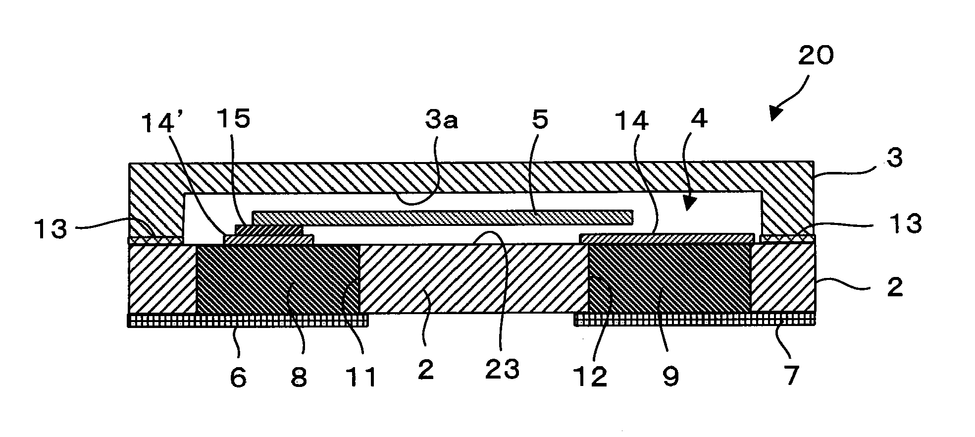
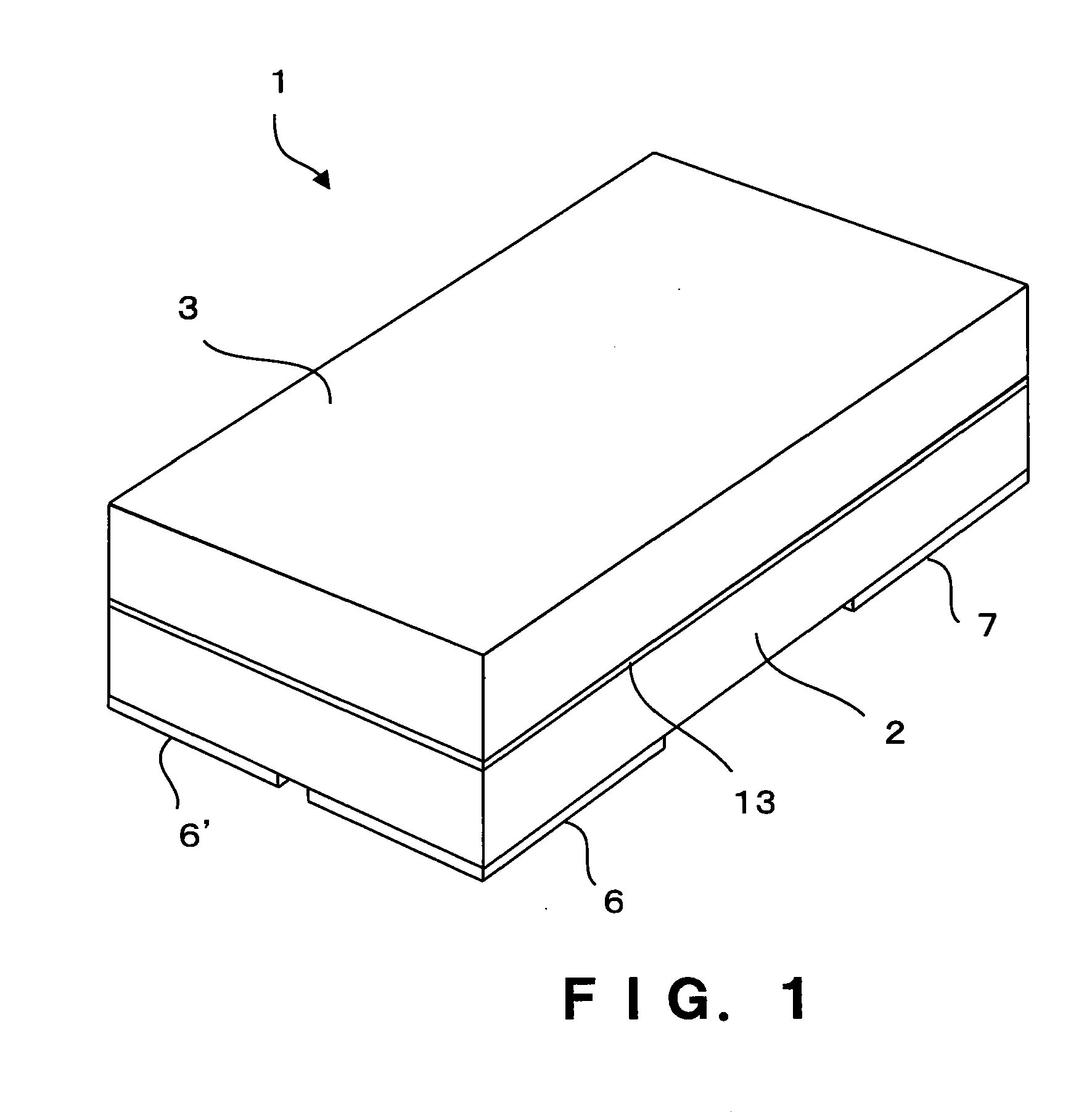
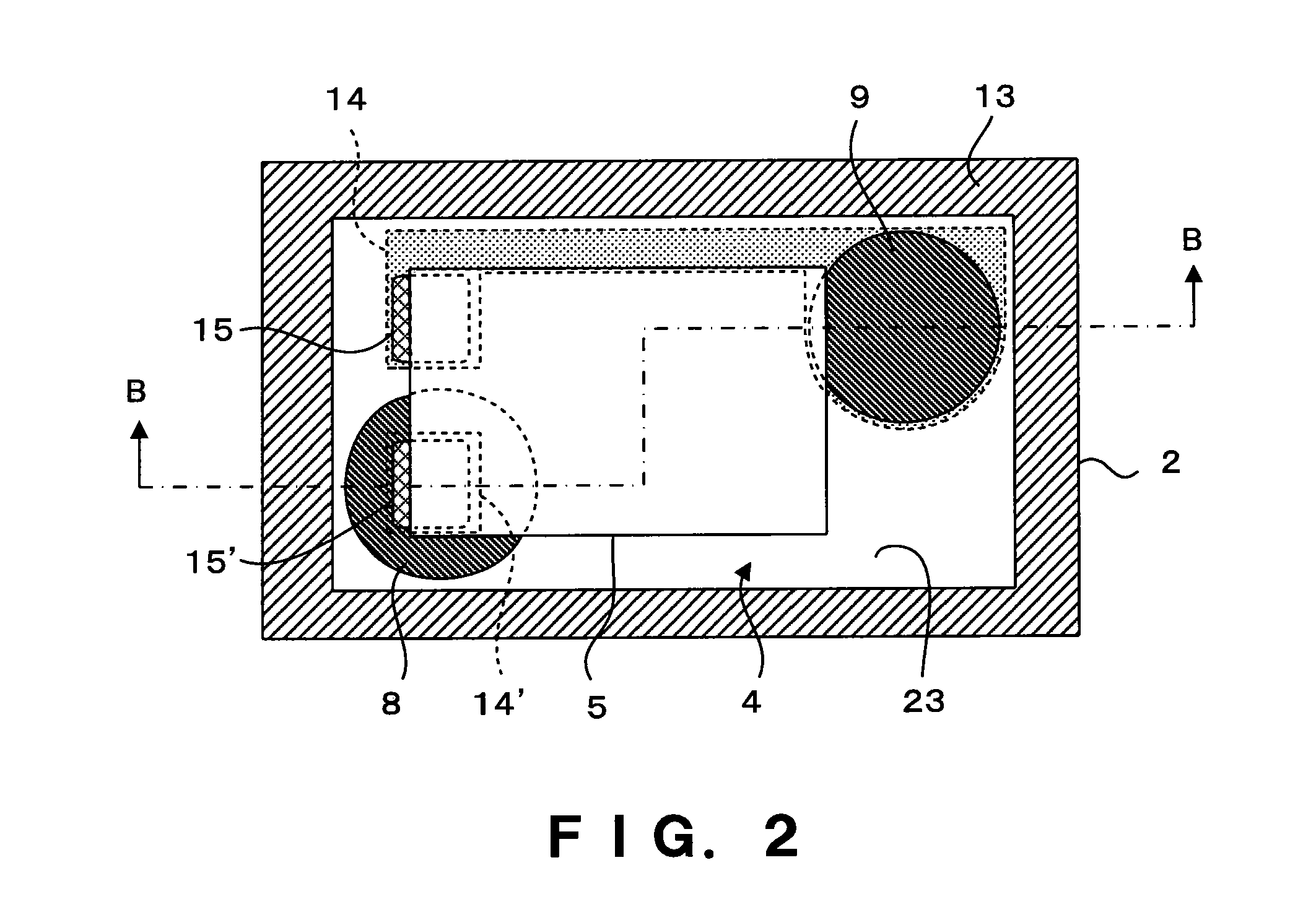
[0046]FIG. 4 is a flowchart illustrating the manufacturing method of the package 1 according to the first embodiment of the invention. The method of manufacturing a package according to the invention is a manufacturing method of the package 1 for bonding the lid substrate 3 on the base substrate 2 made of the glass material, forming the cavity 4 therein, and accommodating an electronic component in the cavity 4 as illustrated in FIGS. 1 to 3.

[0047]First, in a through-hole forming step S1, a glass substrate 10 is prepared, and a plurality of through-holes 11 and 12 is provided in the glass substrate 10. FIG. 5 is a perspective view schematically illustrating the glass substrate 10 in which a plurality of through-holes 11a, 12a, 11b, 12b, and 11c is formed in the through-hole forming step S1. Dotted lines M are cutting lines, and when the glass substrate 10 is cut along the dotted lines M, a plurality of base substrates 2a, 2b, and 2c having the two through-holes 11 and 12 can be obta...

second embodiment

[0055]FIG. 10 is a flowchart illustrating the manufacturing method of the package 1 according to a second embodiment of the invention. FIGS. 11 to 19 are explanatory view for explaining the manufacturing method of the package according to the second embodiment. FIGS. 11 to 13 illustrate a concave portion forming step S1a, FIG. 14 illustrates a penetrating step S1b, FIGS. 15 and 16 illustrate an electrode pin inserting step S2, FIG. 17 is a cross-sectional view schematically illustrating the glass substrate 10 after the welding step S3 and the cooling step S4, and FIGS. 18 and 19 are respectively a cross-sectional view and a top view schematically illustrating the base substrate 2 after the grinding step S5. According to the second embodiment, a method of manufacturing multiple products for simultaneously forming a number of the base substrates 2 from the glass substrate 10 is employed. Like elements which are the same or have the same functions as those above are denoted like refere...

third embodiment

[0065]FIG. 20 is a flowchart illustrating the method of manufacturing a piezoelectric vibrator according to a third embodiment of the invention. A completed drawing of the piezoelectric vibrator is as illustrated in FIGS. 1 to 3. The third embodiment includes a base substrate forming step S10, a lid substrate forming step S20, and a piezoelectric vibrating reed generating step S30. Hereinafter, the workflow will be described.

[0066]First, in a polishing, washing, and etching step S0, a glass substrate is polished and washed, and then the glass substrate is subjected to etching to remove a work-affected layer on its outermost surface. Next, in a through-electrode forming step S9, as in the first or second embodiment, a glass wafer 21 having the through-electrodes 8 and 9 implanted in the glass substrate 10 is formed. The soda-lime glass may be used as the glass material.

[0067]Specifically, in the through-hole forming step S1, a plurality of the through-holes 11 and 12 is provided in t...


PUM

PropertyMeasurementUnit
Temperatureaaaaaaaaaa
Thicknessaaaaaaaaaa
Diameteraaaaaaaaaa

Abstract

Provided is a method of manufacturing a package capable of providing a plurality of through-electrodes in a base substrate made of a glass material with high position precision. An electrode member having a plurality of pins erected on a base is prepared, the plurality of pins is inserted into a plurality of through-holes of a glass substrate provided with the plurality of through-holes, the resultant is heated to a temperature higher than the softening point of the glass substrate to weld the corresponding through-holes and the pins to each other, the glass substrate is ground after cooling to remove the base, and the pins are exposed from both surfaces of the glass substrate, thereby forming through-electrodes which are electrically separated from each other.

Description

RELATED APPLICATIONS[0001]This application claims priority under 35 U.S.C. §119 to Japanese Patent Application No. 2010-024655 filed on Feb. 5, 2010, the entire content of which is hereby incorporated by reference.BACKGROUND OF THE INVENTION[0002]1. Field of the Invention[0003]The present invention relates to a manufacturing method of forming a plurality of through-electrodes adjacent to a substrate and a method of manufacturing a piezoelectric vibrator using the same.[0004]2. Description of the Related Art[0005]In recent years, piezoelectric vibrators using crystals or the like have been used as time sources or timing sources for portable phones or portable information terminal devices. Various types of piezoelectric vibrators are known, and as an example, a surface-mounted piezoelectric vibrator is known. As this type of piezoelectric vibrator, there is one known having a three-layer structure in which a piezoelectric substrate provided with a piezoelectric vibrating reed is inter...

Claims


Application Information

Patent Timeline
IPC IPC(8): H03B5/32H01L41/053H01L41/22H01L23/04H01L23/08H03H3/02H03H9/02
CPCH03H9/1021H01L23/055Y10T29/42H01L21/50H01L21/4803H01L2924/0002H01L2924/00H01L23/48H10N30/101
Inventor TANGE, YOSHIHISAYOSHIDA, YOSHIFUMI
Owner SEIKO INSTR INC
Learn More