Although circulators are extremely efficient devices, conventional circulators have several drawbacks.
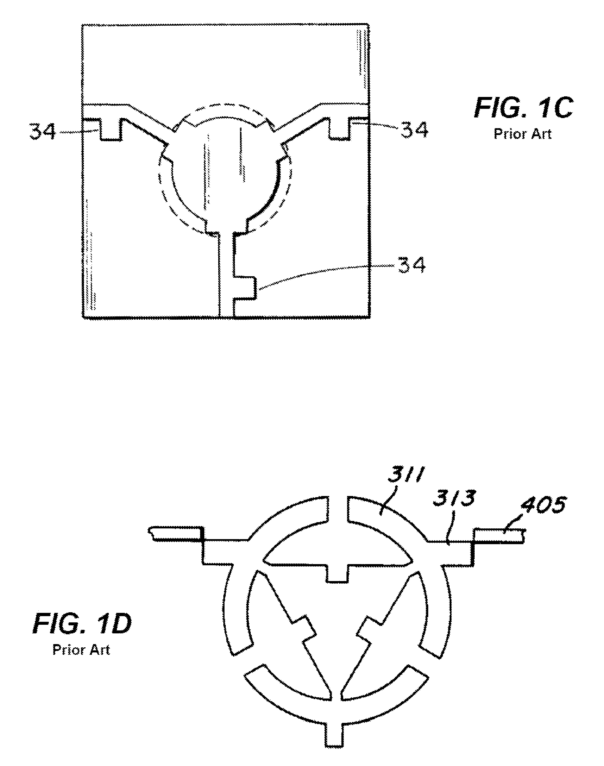
First, installation of conventional circulators on a circuit board requires that an aperture, which is slightly larger than the circulator
package is
cut into the circuit board where the circulator is to be installed.
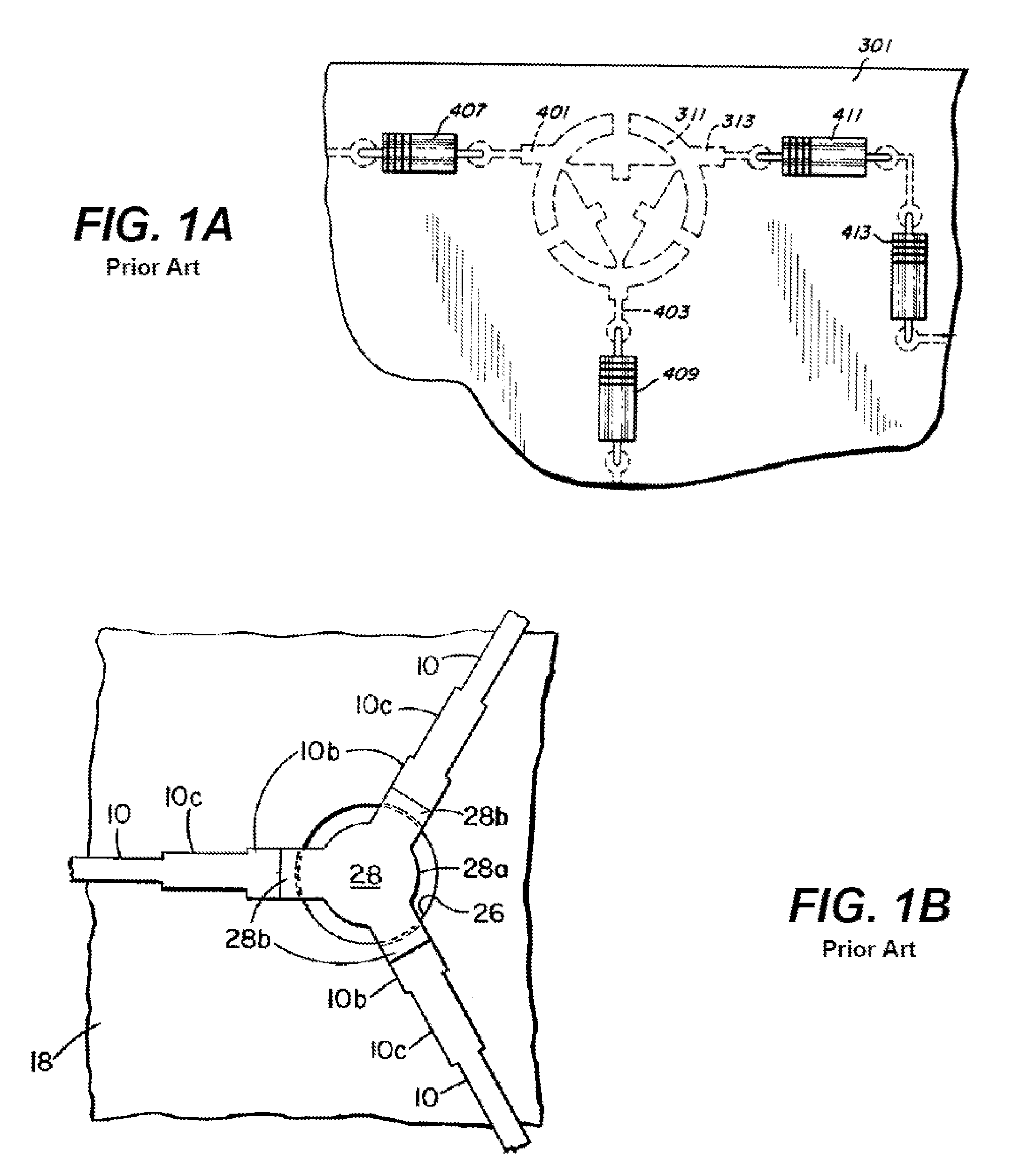
As a result, since the port leads 313, 401, 403 of the circulator are normally made from different materials and have different impendence values from the external components 407, 409, 413, and because these components 407, 409, 413 are soldered to the board, there is an impedance mismatch at the interconnects, which results in a degradation of the
electrical performance of the circulator.
This adds complexity to the manufacturing process and requires tuning based on the operational frequency range of the circulator.
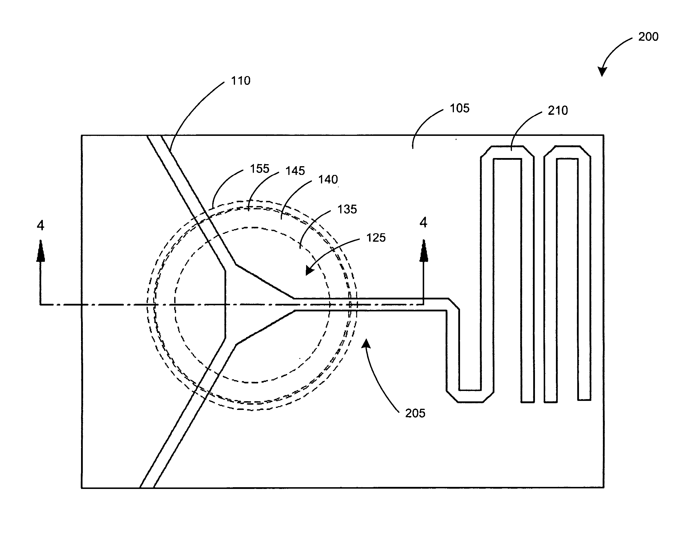
Additionally, discontinuities between the circulator and the circuit trace exist at the connection ports.
The manual interconnects also lead to
insertion losses at the port connectors, an increase in the interference from unwanted RF signals, and high performance variability of the circulator.
Furthermore, the manual interconnects tend to have poor thermal capabilities, which can lead to a decrease in the amount of
signal power that can be passed through the circuit.
Another drawback with conventional circulators is that the circulators do not lie within the same plane as the components of the
external circuit.
This makes it difficult to effectively provide a common ground the circulator and the circuit.
Yet another drawback to conventional circulators is that they are expensive to manufacture and cannot be made using an automated manufacturing process.
For example, the ferrite substrates used in conventional circulators tend to be brittle and can be damaged in an automated manufacturing process.
Unfortunately, this assembly process is expensive in both time and money.
Unfortunately this method still must use manual interconnects to connect the cascaded circulators to an exterior circuit.
Furthermore, the circulator elements are disposed between two ferrite substrates, which are easily damaged.
Although the method uses inexpensive materials, this circulator has several drawbacks.
First, the steel disc covers only a portion of the circulator trace, which provides an inadequate ground for the circulator trace and consequently does not adequately shield the circulator trace from spurious RF signals.
The ground plane between the
external circuit and the circulator must be bridged with ribbon cables, or other suitable connectors, which results in electrical inefficiencies.
Moreover, since the circulator is surface mounted, it uses manual interconnects to connect the circulator to the external circuit, which result in an impedance mismatch between the circulator and the external circuit.

