Power conversion apparatus

a power conversion apparatus and power conversion technology, applied in the direction of electrical apparatus contruction details, instruments, casings/cabinets/drawers, etc., can solve the problems of disadvantageous manufacturing cost, wire breakage, failure of electronic components, etc., to improve the rigidity of the case, reduce external force applied, and improve the effect of maintainability

Active Publication Date: 2011-08-11
DENSO CORP
View PDF28 Cites 35 Cited by
  • Summary
  • Abstract
  • Description
  • Claims
  • Application Information

AI Technical Summary

Benefits of technology

[0016]An embodiment provides a power conversion apparatus which is capable of reducing an external force applied to its electronic components while improving the rigidity of its case, and which is excellent in maintainability, can be effectively mounted, and can be manufactured at low cost.

Problems solved by technology

Accordingly, if the case 94 is not rigid enough, the electronic components fixed to the case 94 may vibrate considerably, causing wire breakage, or failure in the electronic components due to external force applied thereto.
In this case, since the components are fixed directly to the case 94, they may fail due to thermal stress applied to them.
Accordingly, since the case 94 has to be provided with many sealing members, the power conversion apparatus 9 is disadvantageous in manufacturing cost.
In addition, the maintainability of the power conversion apparatus 9 is not good enough in this case, because both the bottom lid 941 and the top lid 942 have to be removed for maintenance work.
However, in this case, the maintainability and rigidity of the case 94 may become worse.
Conversely, since vibration of the engine can transmit to the electronic components through the case 94, wire breakage or fault may occur.
This makes it difficult to improve the productivity, and to prevent reducing the manufacturing cost.
However, when the positions or the projecting directions of the coolant introduction tube and the coolant discharge tube are displaced with reference to the power conversion apparatus 9 (case 94), the coolant introduction tube and the coolant discharge tube are difficult to connect to the coolant pipes in the engine compartment regardless of the accurate positioning of the power conversion apparatus 9 to the mounting portion.
In addition, when forcedly connecting the coolant introduction tube and the coolant discharge tube to the coolant pipes, the coolant introduction tube and the coolant discharge tube interfere with the components around the coolant pipes, which makes it difficult to mount the power conversion apparatus 9.

Method used


Image

  • Power conversion apparatus
  • Power conversion apparatus
  • Power conversion apparatus

Examples


first embodiment

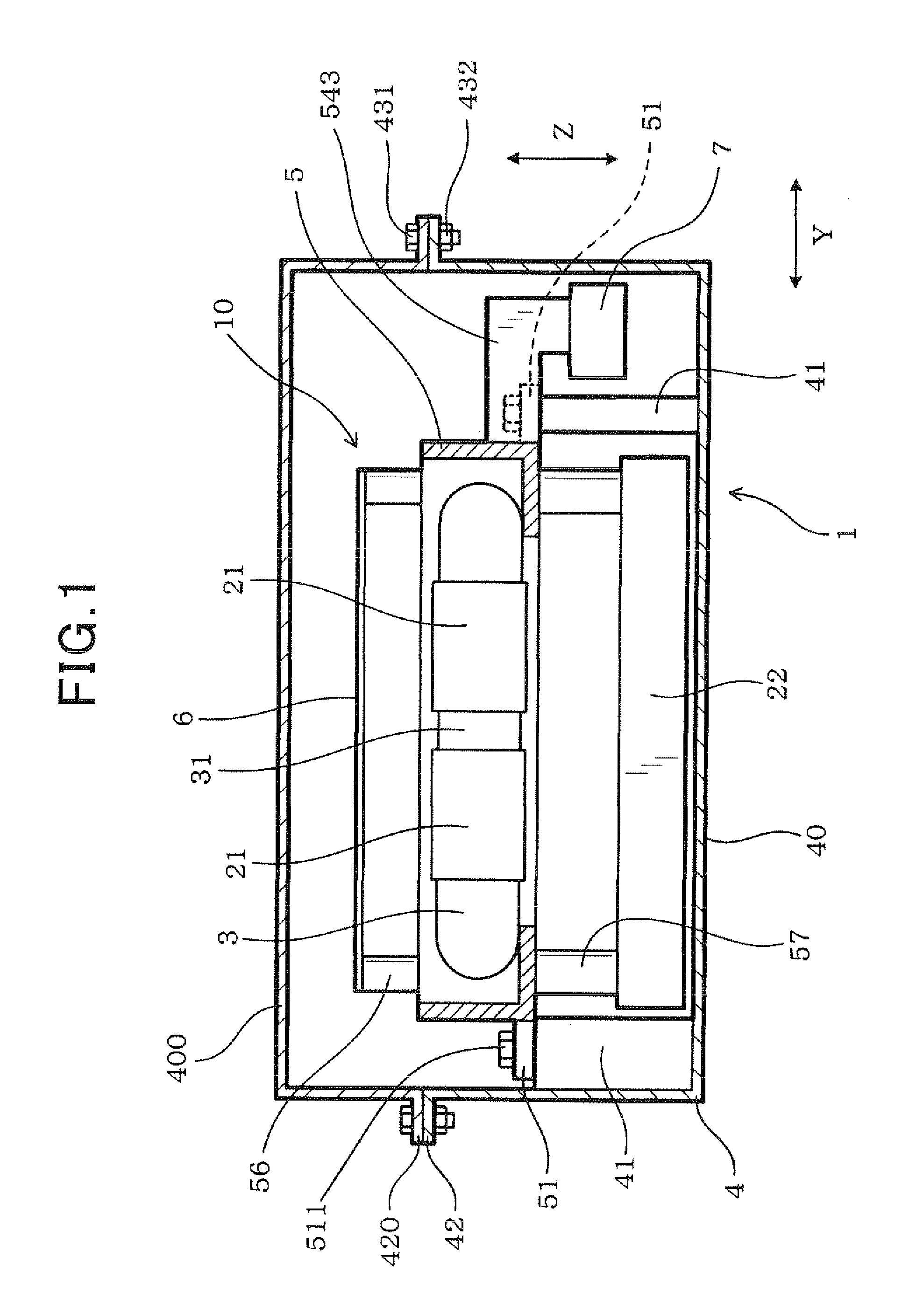
[0062]A power conversion apparatus according to the first embodiment is described with reference to FIGS. 1 to 19.

[0063]As shown in FIG. 1, a power conversion apparatus 1 of this embodiment is constituted of electronic components (semiconductor modules 21, a capacitor 22 and the like) which constitute a power conversion circuit, a cooler 3 for cooling at least part of the electronic components (the semiconductor modules 21 in this embodiment), and a case 4 housing the electronic components and the cooler 3.

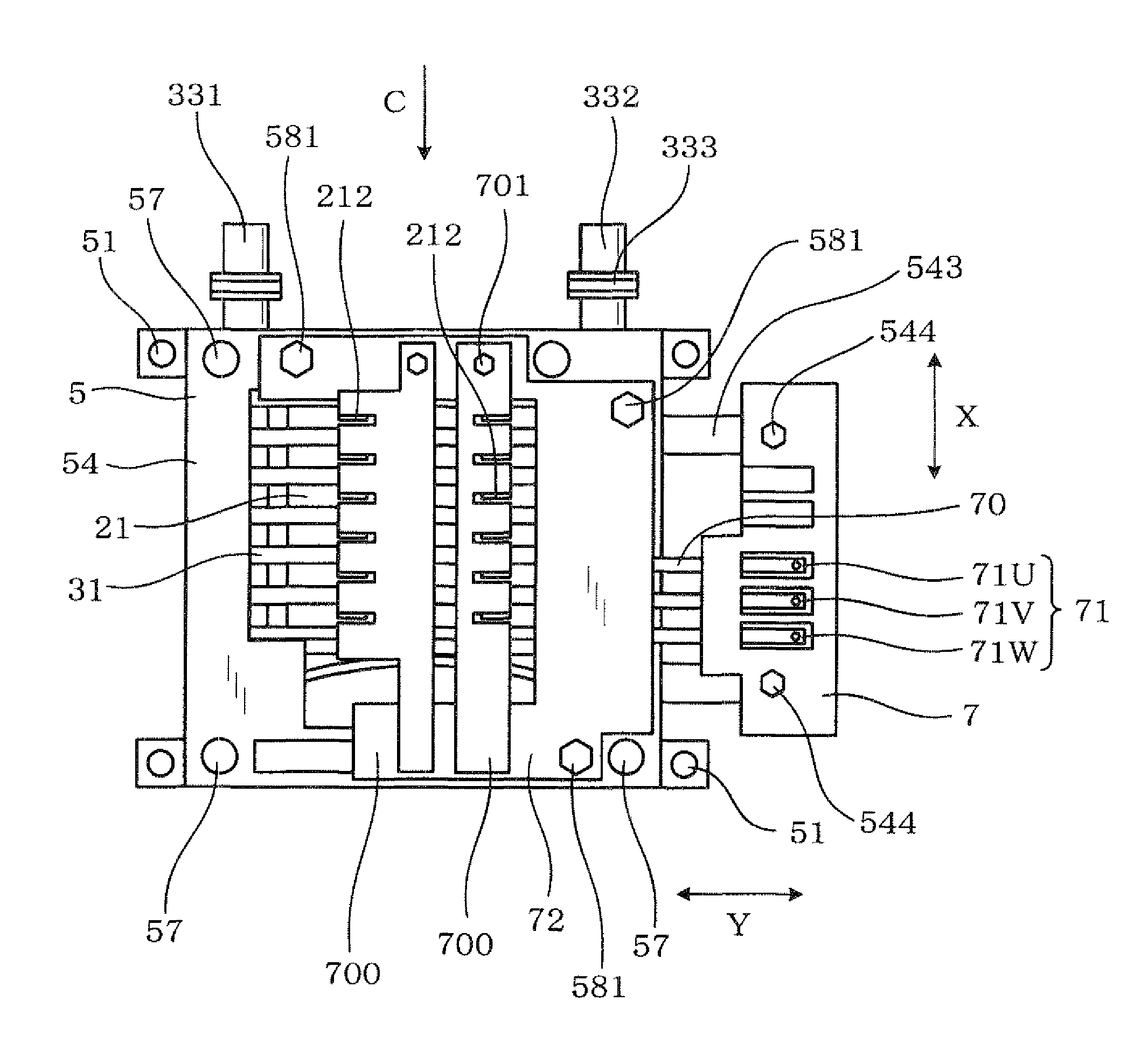
[0064]The semiconductor modules 21 and the cooler 3 are fixed to and integrated with a frame 5 to constitute an internal unit 10. The internal unit 10 is fixed to the case 4, and sealed within the case 4.

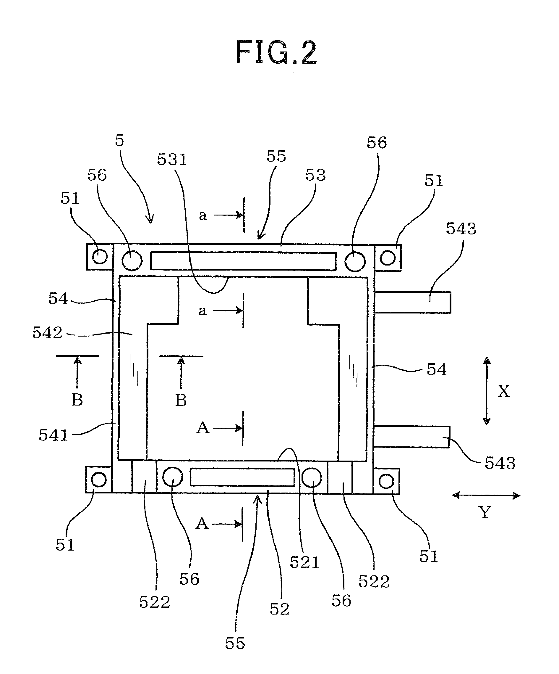
[0065]As shown in FIGS. 16 to 18, the internal unit 10 is fixed to the case 4 through the frame 5. The frame 5 is made of conductive material, and formed in a shape to surround the semiconductor modules 21 constituting the internal unit 10 from all four sides. The frame 5 may be a...

second embodiment

[0148]Next, the second embodiment is described with reference toFIGS. 20 to 26. In the second embodiment, a wire holding section 59 for holding a conductive wire 15 is additionally provided in the frame 5 of the power conversion apparatus 1.

[0149]At least one end of the conductive wire 15 is disposed within the case 4. In this embodiment, the conductive wire 15 connects the capacitor 22 with the control circuit board 6 within the case 4, so that the voltage across the capacitor 22 can be sent to the control circuit board 6 through the conductive wire 15 as a voltage signal indicative of the input voltage of the power conversion apparatus 1.

[0150]The conductive wire 15 is covered with resin except both ends thereof, and has flexibility. The conductive wire 15 is laid outside the is frame 5 to make a connection between the control circuit board 6 and the capacitor 22.

[0151]The wire holding section 59 has a hook-like shape when viewed from the height direction Z as shown in FIGS. 21, 2...

third embodiment

[0158]Next, the third embodiment is described with reference to FIGS.

[0159]27 to 33. In the third embodiment, an electronic component 20 is disposed inside the frame 5 together with the semiconductor modules 21.

[0160]The electronic component 20 is an electronic component other than the semiconductor modules 21, and may be a reactor, capacitor or the like.

[0161]In addition, as shown in FIGS. 27 and 28, the cooler 3 is also disposed inside the frame 5. The power conversion apparatus 1 of this embodiment has a structure in which the semiconductor modules 21 are cooled from one surface thereof by the cooler 3. One surface of the cooling tube 31 constituting the cooler 3 contacts the inner surface 521 of the front wall section 52 of the frame 5. The other surface of the cooling tube 31 contacts the three semiconductor modules 21. The electronic component 20 is disposed between the semiconductor modules 21 and the rear wall section 53 of the frame 5.

[0162]The cooler 3 is formed so that th...


PUM


Abstract

In a power conversion apparatus, electronic components and a cooler are integrated in a frame as an internal unit. The internal unit is fixed within a case through the frame. The frame has such a shape that the electronic components are surrounded by the frame, and includes a first wall section, and second and third wall sections extending from both sides of the first wall section. The cooler includes a coolant introduction tube and a coolant discharge tube. The coolant introduction tube and the coolant discharge tube project outward from to the frame. The first to third wall sections include a support wall section supporting at least one of the coolant introduction tube and the coolant discharge tube, and a frame wall section not supporting the coolant introduction tube and the coolant discharge tube. The thickness of the support wall section is larger than the thickness of the frame wall section.

Description

CROSS-REFERENCE TO RELATED APPLICATION[0001]This application is based on and claims the benefit of priority from earlier Japanese Patent Applications No. 2010-24557 filed Feb. 5, 2010, and No. 2010-244596 filed Oct. 29, 2010, the descriptions of which are incorporated herein by reference.BACKGROUND[0002]1. Technical Field[0003]The present invention relates to a power conversion apparatus in which electronic components configuring a power conversion circuit and a cooler for cooling at least part of the electronic components are housed in its case.[0004]2. Related Art[0005]An electric vehicle or a hybrid vehicle is equipped with a power conversion apparatus such as an inverter or a converter to convert source power into driving power for a drive motor. As shown in FIG. 41, such a power conversion apparatus 9 includes various electronic components including semiconductor modules 921 each incorporating therein switching elements, and a capacitor 922. The electronic components constitute...

Claims


Application Information

Patent Timeline
Patent Type & Authority Applications(United States)
IPC IPC(8): H05K7/20
CPCH01L23/4093H01L23/473H02M7/003H05K7/20854H01L2924/0002H05K7/20927H01L2924/00H01L23/40H01L23/4012
Inventor NAKASAKA, AKIRAOOHAMA, KENICHI
Owner DENSO CORP
Why Eureka
Try Eureka