Power conversion apparatus
a power conversion apparatus and power conversion technology, applied in the direction of printed circuit board receptacles, electrical apparatus construction details, support structure mounting, etc., can solve the problems of disadvantageous manufacturing cost, wire breakage, failure of electronic components, etc., to improve the rigidity of the case, reduce external force applied, and improve the effect of maintainability
- Summary
- Abstract
- Description
- Claims
- Application Information
AI Technical Summary
Benefits of technology
Problems solved by technology
Method used
Image
Examples
first embodiment
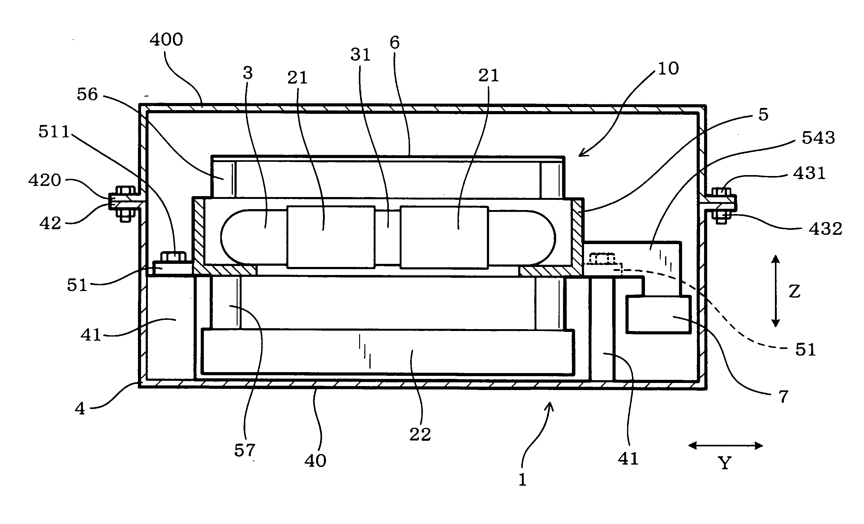
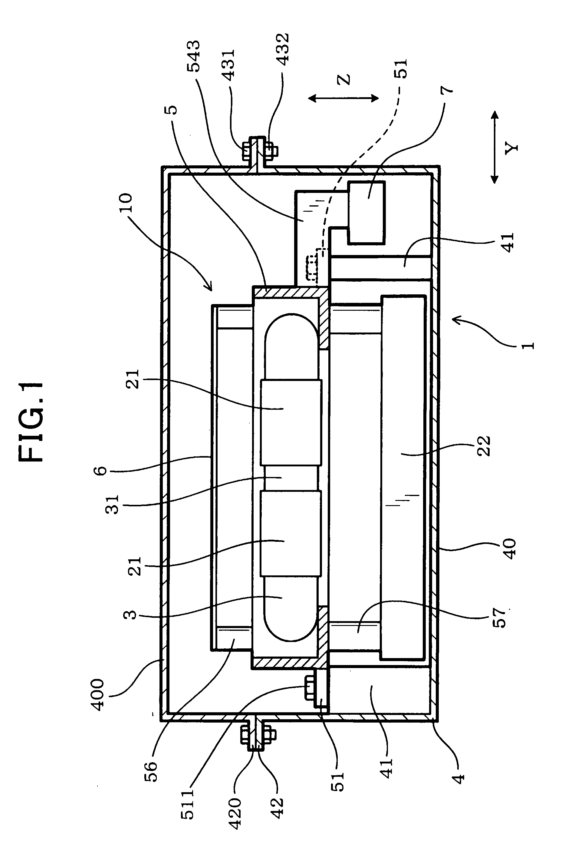
[0048]A power conversion apparatus according to the first embodiment is described with reference to FIGS. 1 to 19.
[0049]As shown in FIG. 1, a power conversion apparatus 1 of this embodiment is constituted of electronic components (semiconductor modules 21, a capacitor 22 and the like) which constitute a power conversion circuit, a cooler 3 for cooling at least part of the electronic components (the semiconductor modules 21 in this embodiment), and a case 4 housing the electronic components and the cooler 3.
[0050]The semiconductor modules 21 and the cooler 3 are fixed to and integrated with a frame 5 to constitute an internal unit 10. The internal unit 10 is fixed to the case 4, and sealed within the case 4.
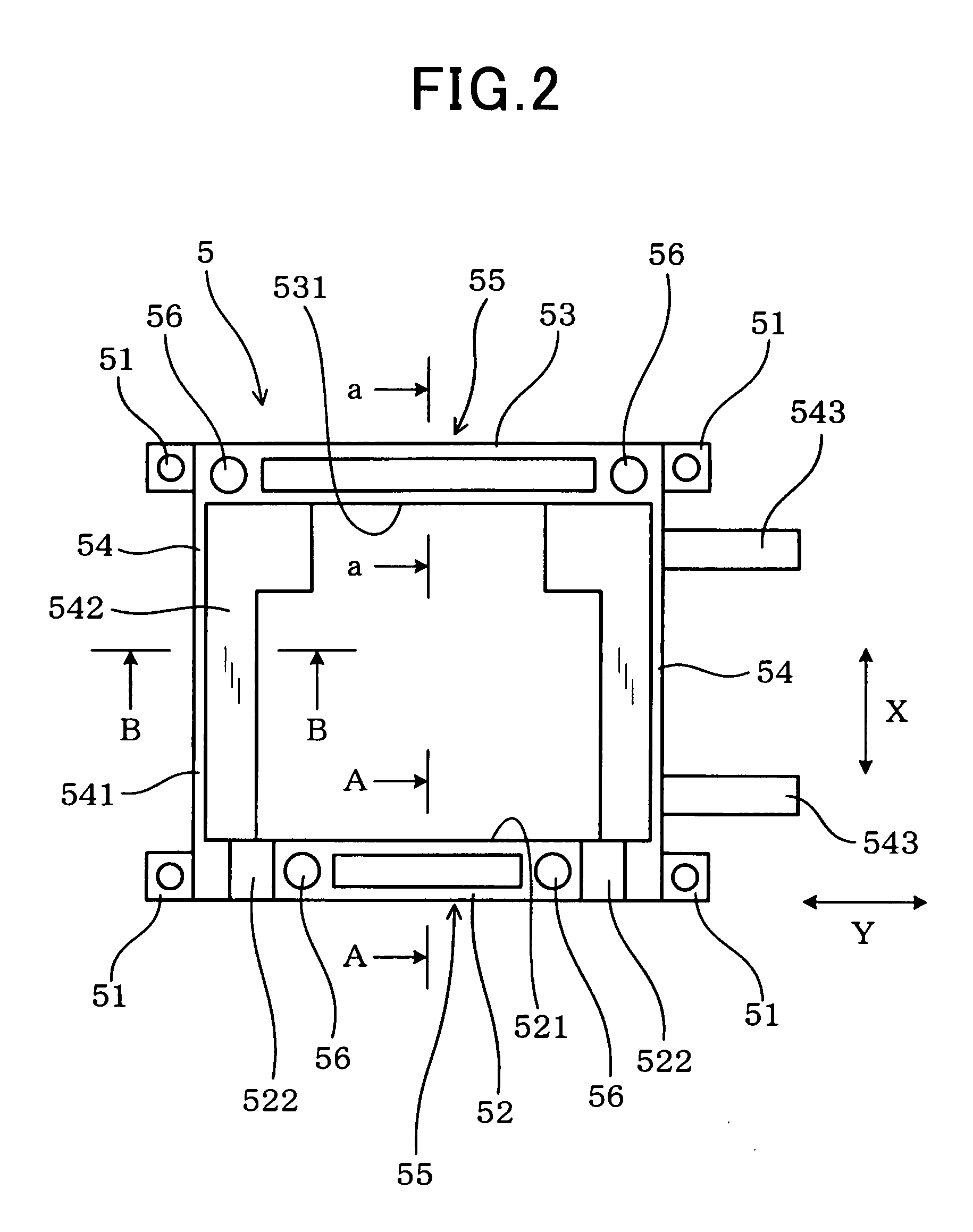
[0051]As shown in FIGS. 16 to 18, the internal unit 10 is fixed to the case 4 through the frame 5. The frame 5 is made of conductive material, and formed in a shape to surround the semiconductor modules 21 constituting the internal unit 10 from all four sides. The frame 5 may be a...
second embodiment
[0135]Next, the second embodiment is described with reference to FIGS. 20 to 26. In the second embodiment, a wire holding section 59 for holding a conductive wire 15 is additionally provided in the frame 5 of the power conversion apparatus 1.
[0136]At least one end of the conductive wire 15 is disposed within the case 4. In this embodiment, the conductive wire 15 connects the capacitor 22 with the control circuit board 6 within the case 4, so that the voltage across the capacitor 22 can be sent to the control circuit board 6 through the conductive wire 15 as a voltage signal indicative of the input voltage of the power conversion apparatus 1.
[0137]The conductive wire 15 is covered with resin except both ends thereof, and has flexibility. The conductive wire 15 is laid outside the frame 5 to make a connection between the control circuit board 6 and the capacitor 22.
[0138]The wire holding section 59 has a hook-like shape when viewed from the height direction Z as shown in FIGS. 21, 23,...
third embodiment
[0145]Next, the third embodiment is described with reference to FIGS. 27 to 29. In the power conversion apparatus 1 of the third embodiment, the unit fixing sections 51 of the frame 5 project outward in the stacking direction X from the front wall section 52 and the rear wall section 53.
[0146]In this embodiment, as shown in FIG. 27, four unit fixing sections 51 diagonally project outward from four corners of the frame 5, and one unit fixing section 51 projects forward from the front wall section 52, when viewed from the height direction Z. That is, the unit fixing sections 51 provided at the four corners of the frame 5 project outward in the stacking direction X from the front wall section 52 and the rear wall section 53, and project outward in the lateral direction Y from the pair of side wall sections 54. The unit fixing section 51 provided on the front wall section 52 is disposed between the pair of concave portions 522 provided in the front wall section 52, that is, between the ...
PUM
 Abstract
Description
Claims
Application Information
 - R&D
- Intellectual Property
- Life Sciences
- Materials
- Tech Scout
- Unparalleled Data Quality
- Higher Quality Content
- 60% Fewer Hallucinations
Browse by: Latest US Patents, China's latest patents, Technical Efficacy Thesaurus, Application Domain, Technology Topic, Popular Technical Reports.
© 2025 PatSnap. All rights reserved.Legal|Privacy policy|Modern Slavery Act Transparency Statement|Sitemap|About US| Contact US: help@patsnap.com


