Efficiency improvements for liquid ring pumps

a technology of liquid ring pump and efficiency improvement, which is applied in the direction of pump components, non-positive displacement pumps, jet pumps, etc., can solve the problems of fluid friction and energy loss of liquid ring pumps, and achieve the effect of reducing fluid friction losses in the pump and reducing drag

Inactive Publication Date: 2011-08-11
GARDNER DENVER NASH
View PDF40 Cites 6 Cited by
  • Summary
  • Abstract
  • Description
  • Claims
  • Application Information

AI Technical Summary

Benefits of technology

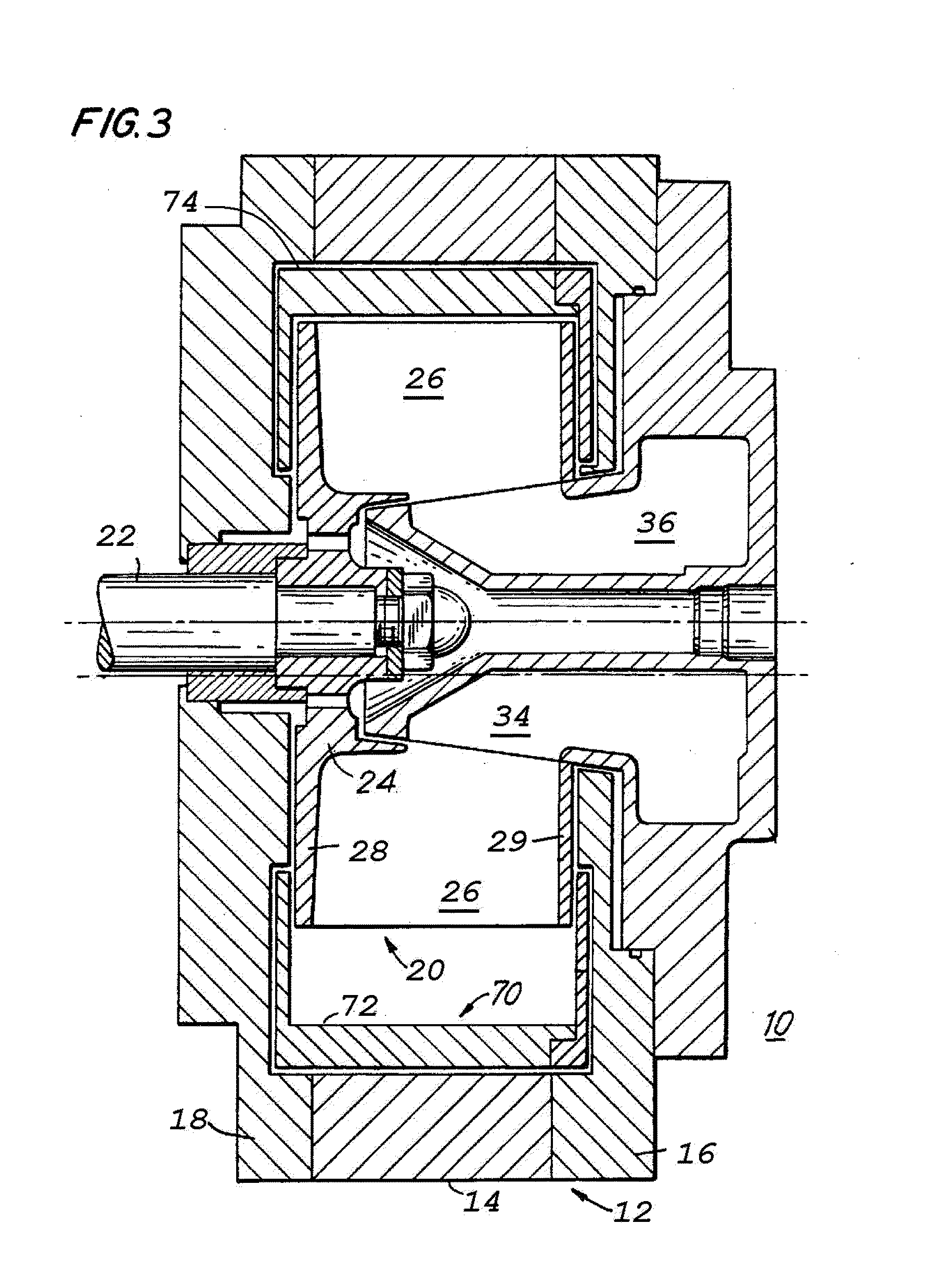
[0005]Embodiments of this invention provide a liquid ring pump in which at least portions of the pump have textured surfaces to reduce fluid friction losses in the pump. The surfaces of the interior of the pump in contact with a fluid can be configured to provide for drag reduction. In one aspect, at least a portion of at least one surface of the interior of the pump in contact with a fluid can be configured to modify the fluid boundary layer on the surface. In another aspect, at least a portion of at least one surface of the interior of the pump in contact with a fluid can be configured to control separation of the fluid boundary layer.

Problems solved by technology

It is known that a major cause of energy loss in liquid ring pumps is fluid friction between the fluids within the pump and the design / configuration of the “wetted area” (the surface area inside of the pump exposed to fluid, such as the working liquid forming the liquid ring and / or the gas being pumped) of the pump due to drag.

Method used


Image

  • Efficiency improvements for liquid ring pumps
  • Efficiency improvements for liquid ring pumps
  • Efficiency improvements for liquid ring pumps

Examples


Embodiment Construction

[0015]The present invention can be understood more readily by reference to the following detailed description, examples, drawings, and claims, and their previous and following description. However, before the present devices, systems, and / or methods are disclosed and described, it is to be understood that this invention is not limited to the specific devices, systems, and / or methods disclosed unless otherwise specified, as such can, of course, vary. It is also to be understood that the terminology used herein is for the purpose of describing particular aspects only and is not intended to be limiting.

[0016]The following description of the invention is provided as an enabling teaching of the invention in its best, currently known embodiment. To this end, those skilled in the relevant art will recognize and appreciate that many changes can be made to the various aspects of the invention described herein, while still obtaining the beneficial results of the present invention. It will als...


PUM


Abstract

The present invention is directed to a textured surface that provides for drag reduction, and therefore efficiency improvements in a liquid ring pump. At least a portion of the surfaces of the pump that contact fluid therein the pump are textured to control boundary layer separation. The texture can be a plurality of dimples are defined therein the surface. The dimples have a predetermined shape, size, density and pattern.

Description

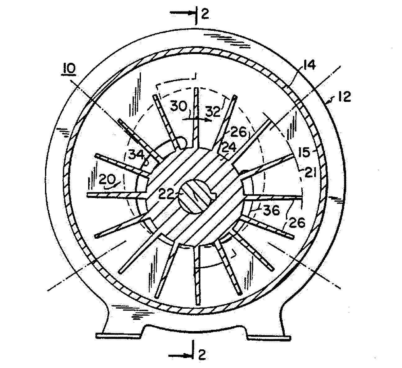
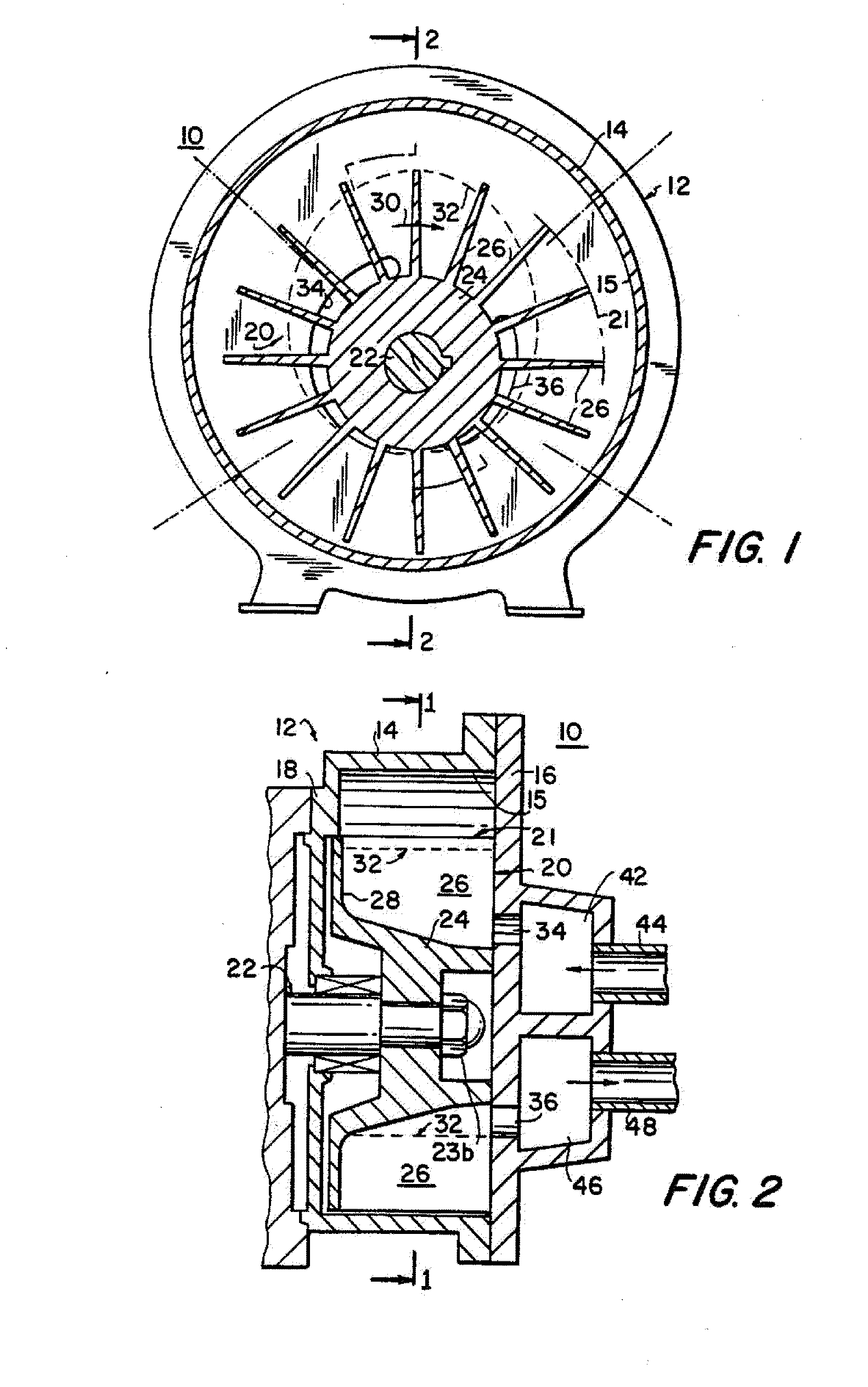
FIELD OF THE INVENTION[0001]This invention relates to liquid ring pumps, and more particularly to liquid ring pumps in which at least portions of the pump have textured surfaces to reduce fluid frictional losses in the pumps.BACKGROUND[0002]In conventional liquid ring pumps, a rotor is rotatably mounted in a stationary annular housing so that the rotor axis is eccentric to the central axis of the housing. The rotor has blades which extend parallel to the rotor axis and which project outward radially from the rotor axis so that the blades are equally spaced in the circumferential direction around the rotor. A quantity of pumping liquid (usually water) is maintained in the housing so that as the rotor rotates, the rotor blades engage the liquid and form it into an annular ring inside the housing. Because the housing is eccentric to the rotor, the liquid ring is also eccentric to the rotor. This means that on one side of the pump (the so-called intake zone), the liquid between adjacent...

Claims


Application Information

Patent Timeline
Patent Type & Authority Applications(United States)
IPC IPC(8): F04C19/00
CPCF04C19/00F04C2240/30F04C2230/92
Inventor SHENOI, RAMESH B.LENGYEL, LOUIS J.DIAKOMIS, ATHANASIOS
Owner GARDNER DENVER NASH
Why Eureka
Try Eureka