

Hybrid interface for serial and parallel communication
a serial and parallel communication technology, applied in the field of data communication, can solve the problems of significant power saving, waste of power, and inability to start up the cdr and reference oscillator components, and achieve the effects of reducing pin count, saving power, and improving reliability
- Summary
- Abstract
- Description
- Claims
- Application Information
AI Technical Summary
Benefits of technology
Problems solved by technology
Method used
Image

Examples
Embodiment Construction
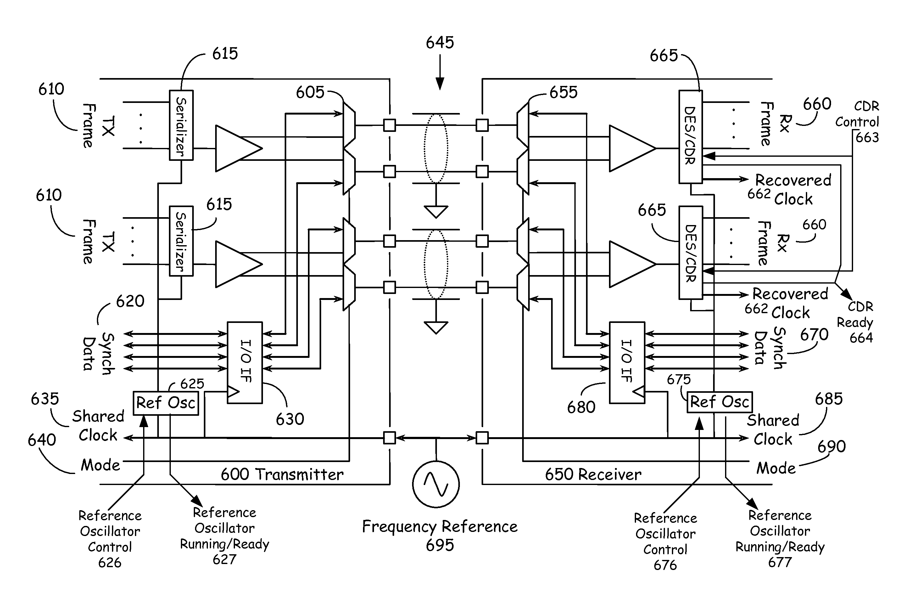
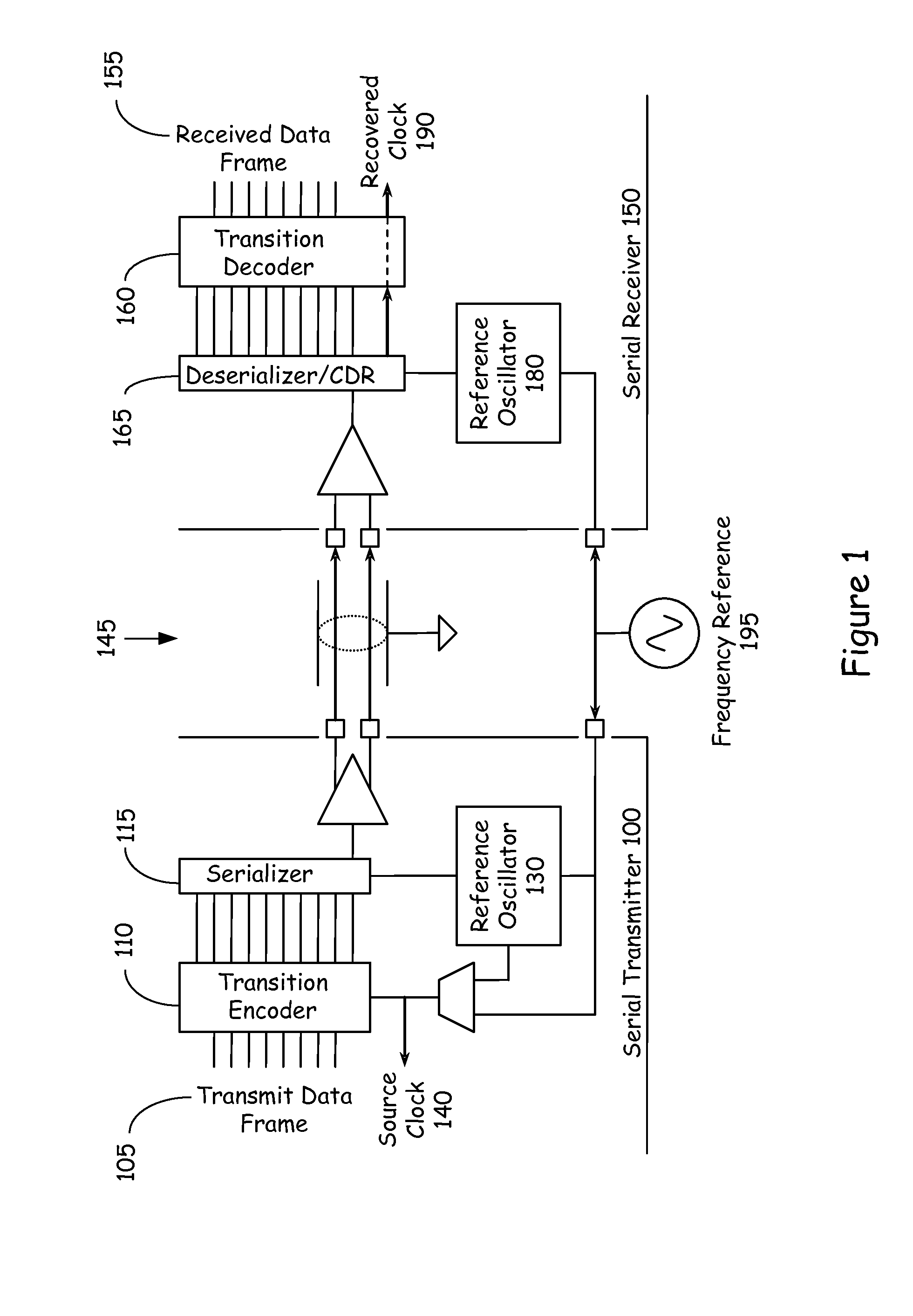
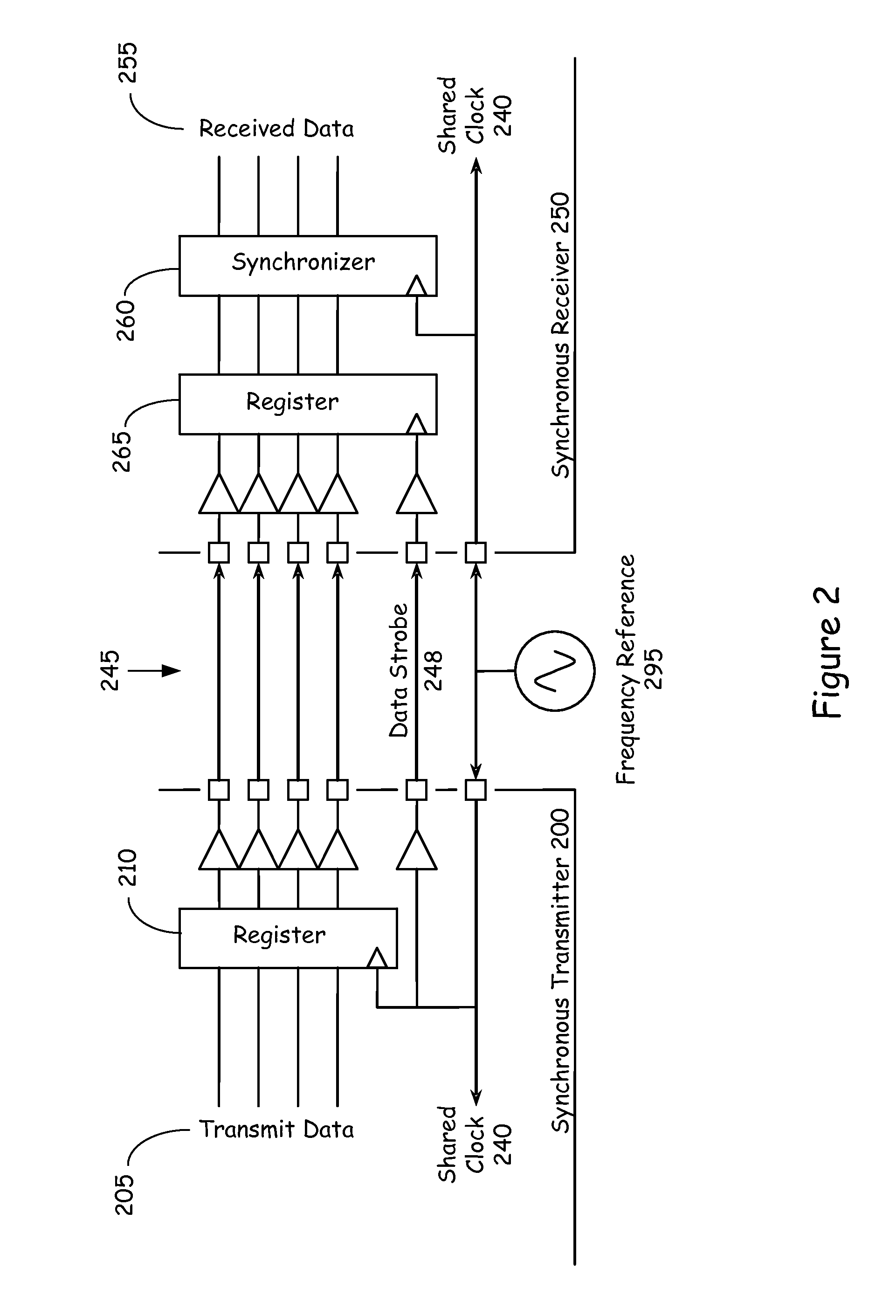
Embodiments of the invention are generally directed to a hybrid interface for serial and parallel communication.
In some embodiments, a method, apparatus, or system provides for a hybrid interface for serial and parallel communication.
In some embodiments, a hybrid interface provides for sharing pins between interfaces, such as between a CDR-style serial interface and a bit-wise parallel interface. In an implementation, a parallel interface may run at a significantly lower speed than a serial interface, but the parallel interface has negligible start-up latency in comparison with the serial interface, and does not use the CDR component, thus saving power consumption. Further, the parallel interface may operate without additional reference oscillator components, saving further power. In some embodiments, communication latency may be reduced by elimination of bit-wise serialization, framing, and the coding (such as 8b / 10b (mapping 8 bit symbols to 10 bit symbols), 17b / 20b, or 64b / 66b co...
PUM
 Abstract
Description
Claims
Application Information